EVAL-ADUC831QSZ Analog Devices Inc, EVAL-ADUC831QSZ Datasheet - Page 26
EVAL-ADUC831QSZ
Manufacturer Part Number
EVAL-ADUC831QSZ
Description
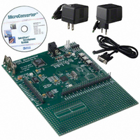
KIT DEV FOR ADUC831 QUICK START
Manufacturer
Analog Devices Inc
Series
QuickStart™ Kitr
Type
MCUr
Datasheet
1.EVAL-ADUC831QSZ.pdf
(76 pages)
Specifications of EVAL-ADUC831QSZ
Contents
Evaluation Board, Power Supply, Cable, Software and Documentation
Silicon Manufacturer
Analog Devices
Core Architecture
8051
Silicon Core Number
ADuC831
Tool / Board Applications
General Purpose MCU, MPU, DSP, DSC
Mcu Supported Families
ADUC8xx
Development Tool Type
Hardware - Eval/Demo Board
Rohs Compliant
Yes
Lead Free Status / RoHS Status
Lead free / RoHS Compliant
For Use With/related Products
ADuC831
Lead Free Status / Rohs Status
Compliant
Other names
EVAL-ADUC831QS
EVAL-ADUC831QS
EVAL-ADUC831QS


ADuC831
INITIATING CALIBRATION IN CODE
When calibrating the ADC, using ADCCON1 the ADC should
be set up into the configuration in which it will be used. The
ADCCON3 register can then be used to set the device up and
calibrate the ADC offset and gain.
MOV ADCCON1,#08CH
To calibrate device offset:
MOV ADCCON2,#0BH
MOV ADCCON3,#25H
To calibrate device gain:
MOV ADCCON2,#0CH
MOV ADCCON3,#27H
To calibrate system offset:
Connect system AGND to an ADC channel input (0).
MOV ADCCON2,#00H
MOV ADCCON3,#25H
;ADC on; ADCCLK set
;to divide by 16, 4
;acquisition clock
;select internal AGND
;select offset calibration,
;31 averages per bit,
;offset calibration
;select internal VREF
;select offset calibration,
;31 averages per bit,
;offset calibration
;select external AGND
;select offset calibration,
;31 averages per bit
–26–
To calibrate system gain:
Connect system V
MOV ADCCON2,#01H
MOV ADCCON3,#27H
The calibration cycle time, T
equation assuming a 16 MHz crystal:
For an ADCCLK/F
NUMAV = 15, the calibration cycle time is:
In a calibration cycle the ADC busy flag (Bit 7), instead of
framing an individual ADC conversion as in normal mode, will
go high at the start of calibration and only return to zero at the
end of the calibration cycle. It can therefore be monitored in
code to indicate when the calibration cycle is completed. The
following code can be used to monitor the BUSY signal during
a calibration cycle:
WAIT:
MOV A, ADCCON3
JB ACC.7, WAIT
T
CAL
T
T
CAL
CAL
=
14
=
=
14
4 2
×
REF
.
CORE
ADCCLK
×
ms
to an ADC channel input (1).
( /
1 1000000
divide ratio of 16, a T
;move ADCCON3 to A
;If Bit 7 is set jump to
;select external VREF
;select offset calibration,
;31 averages per bit,
;offset calibration
WAIT else continue
CAL
×
, is calculated by the following
NUMAV
)
×
15
×
×
ACQ
(
16
(
16 4
= 4 ADCCLK,
+
+
T
ACQ
)
REV. 0
)
Related parts for EVAL-ADUC831QSZ
Image
Part Number
Description
Manufacturer
Datasheet
Request
R


Part Number:
Description:
BOARD EVAL FOR SI270X-A
Manufacturer:
Silicon Laboratories Inc
Datasheet:

Part Number:
Description:
BUCK CONV REF DESIGN KIT IP1201
Manufacturer:
International Rectifier
Datasheet:
Part Number:
Description:
BOARD DEMO SYNC DUAL BUCK CNVTER
Manufacturer:
International Rectifier
Datasheet:
Part Number:
Description:
BOARD DEMO SYNC BUCK CONVETER
Manufacturer:
International Rectifier
Datasheet:

Part Number:
Description:
EVALBOARD/EB Omnidirectional microphone - Analog
Manufacturer:
Analog Devices
Datasheet:
Part Number:
Description:
EVALBOARD/EB Omnidirectional microphone - Analog
Manufacturer:
Analog Devices
Datasheet:


Part Number:
Description:
BOARD EVAL LED DRIVER LT3756
Manufacturer:
Linear Technology
Datasheet:

Part Number:
Description:
BOARD EVAL FOR AD7741/7742
Manufacturer:
Analog Devices Inc
Datasheet:

Part Number:
Description:
±1.7g Dual-Axis IMEMS Accelerometer Evaluation Board
Manufacturer:
Analog Devices Inc
Datasheet:

Part Number:
Description:
IC MULTIPLIER ANALOG 8-SOIC T/R
Manufacturer:
Analog Devices Inc
Datasheet:

Part Number:
Description:
IC ANALOG MULTIPLIER 8-DIP
Manufacturer:
Analog Devices Inc
Datasheet:
Part Number:
Description:
IC ANALOG MULTIPLIER 8-SOIC
Manufacturer:
Analog Devices Inc
Datasheet:
Part Number:
Description:
IC ANALOG MULTIPLIER 8-DIP
Manufacturer:
Analog Devices Inc
Datasheet: