EVAL-ADUC831QSZ Analog Devices Inc, EVAL-ADUC831QSZ Datasheet - Page 57
EVAL-ADUC831QSZ
Manufacturer Part Number
EVAL-ADUC831QSZ
Description
KIT DEV FOR ADUC831 QUICK START
Manufacturer
Analog Devices Inc
Series
QuickStart™ Kitr
Type
MCUr
Datasheet
1.EVAL-ADUC831QSZ.pdf
(76 pages)
Specifications of EVAL-ADUC831QSZ
Contents
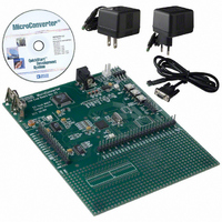
Evaluation Board, Power Supply, Cable, Software and Documentation
Silicon Manufacturer
Analog Devices
Core Architecture
8051
Silicon Core Number
ADuC831
Tool / Board Applications
General Purpose MCU, MPU, DSP, DSC
Mcu Supported Families
ADUC8xx
Development Tool Type
Hardware - Eval/Demo Board
Rohs Compliant
Yes
Lead Free Status / RoHS Status
Lead free / RoHS Compliant
For Use With/related Products
ADuC831
Lead Free Status / Rohs Status
Compliant
Other names
EVAL-ADUC831QS
EVAL-ADUC831QS
EVAL-ADUC831QS


Timer 1 Generated Baud Rates
When Timer 1 is used as the baud rate generator, the baud rates
in Modes 1 and 3 are determined by the Timer 1 overflow rate
and the value of SMOD as follows:
The Timer 1 interrupt should be disabled in this application. The
Timer itself can be configured for either timer or counter opera-
tion, and in any of its three running modes. In the most typical
application, it is configured for timer operation in the Autoreload
mode (high nibble of TMOD = 0010 binary). In that case, the baud
rate is given by the formula:
Table XXIV shows some commonly used baud rates and how they
might be calculated from a core clock frequency of 11.0592 MHz
and 12 MHz. Generally speaking, a 5% error is tolerable using
asynchronous (start/stop) communications.
Ideal
Baud
9600
19200
9600
2400
Timer 2 Generated Baud Rates
Baud rates can also be generated using Timer 2. Using Timer 2 is
similar to using Timer 1 in that the timer must overflow 16 times
before a bit is transmitted/received. Because Timer 2 has a 16-bit
REV. 0
Table XXIV. Commonly-Used Baud Rates, Timer 1
(
Modes
2
Core
CLK
(MHz)
12
11.0592
11.0592
11.0592
SMOD
(
Modes
2
SMOD
1
/
NOTE: OSC. FREQ. IS DIVIDED BY 2, NOT 12.
NOTE: AVAILABILITY OF ADDITIONAL
EXTERNAL INTERRUPT
and
32
TRANSITION
T2EX
DETECTOR
PIN
PIN
1
1
1
0
0
CORE
/
) (
T2
SMOD TH1-Reload Actual
Value
CLK
32
×
3
and
Baud Rate =
Core Clock / (
) (Timer Overflow Rate)
×
3
Baud Rate =
2
Value
–7
–3
–3
–12 (F4H)
1
(FDH)
(F9H)
(FDH)
C/ T2 = 0
C/ T2 = 1
12
×
EXEN2
[
256
CONTROL
CONTROL
Figure 53. Timer 2, UART Baud Rates
Baud
8929
19200
9600
2400
– TH
TR2
1
EXF 2
]))
%
Error
7
0
0
0
RCAP2L
(8 BITS)
TL2
TIMER 2
INTERRUPT
–57–
RCAP2H
(8 BITS)
Autoreload mode, a wider range of baud rates is possible using
Timer 2.
Therefore, when Timer 2 is used to generate baud rates, the timer
increments every two clock cycles and not every core machine
cycle as before. Thus, it increments six times faster than Timer 1,
and therefore baud rates six times faster are possible. Because
Timer 2 has 16-bit autoreload capability, very low baud rates are
still possible.
Timer 2 is selected as the baud rate generator by setting the TCLK
and/or RCLK in T2CON. The baud rates for transmit and receive
can be simultaneously different. Setting RCLK and/or TCLK puts
Timer 2 into its baud rate generator mode as shown in Figure 53.
In this case, the baud rate is given by the formula:
Table XXV shows some commonly used baud rates and how they
might be calculated from a core clock frequency of 11.0592 MHz
and 12 MHz.
Ideal
Baud
19200 12
9600
2400
1200
19200 11.0592 –1 (FFH)
9600
2400
1200
Modes
TH2
(Core Clk)/(
Modes 1 and 3 Baud Rate =
Table XXV. Commonly Used Baud Rates, Timer 2
RELOAD
OVERFLOW
1
Core
CLK
(MHz)
12
12
12
11.0592 –1 (FFH)
11.0592 –1 (FFH)
11.0592 –2 (FFH)
TIMER 2
and
3
Baud Rate = ( /
32
RCAP2H
Value
–1 (FFH)
–1 (FFH)
–1 (FFH)
–2 (FEH)
1
1
× [
OVERFLOW
2
65536
TIMER 1
0
0
0
1
1 16
– RCAP H, RCAP L
RCAP2L
Value
–20 (ECH)
–41 (D7H)
–164 (5CH)
–72 (B8H)
–18 (EEH)
–36 (DCH) 9600
–144 (70H)
–32 (E0H)
RCLK
TCLK
(
16
16
) (Timer
SMOD
×
2
RX
CLOCK
TX
CLOCK
ADuC831
2
Actual %
Baud
19661
9591
2398
1199
19200
2400
1200
Overflow Rate)
2
)])
Error
2.4
0.1
0.1
0.1
0
0
0
0
Related parts for EVAL-ADUC831QSZ
Image
Part Number
Description
Manufacturer
Datasheet
Request
R


Part Number:
Description:
BOARD EVAL FOR SI270X-A
Manufacturer:
Silicon Laboratories Inc
Datasheet:

Part Number:
Description:
BUCK CONV REF DESIGN KIT IP1201
Manufacturer:
International Rectifier
Datasheet:
Part Number:
Description:
BOARD DEMO SYNC DUAL BUCK CNVTER
Manufacturer:
International Rectifier
Datasheet:
Part Number:
Description:
BOARD DEMO SYNC BUCK CONVETER
Manufacturer:
International Rectifier
Datasheet:

Part Number:
Description:
EVALBOARD/EB Omnidirectional microphone - Analog
Manufacturer:
Analog Devices
Datasheet:
Part Number:
Description:
EVALBOARD/EB Omnidirectional microphone - Analog
Manufacturer:
Analog Devices
Datasheet:


Part Number:
Description:
BOARD EVAL LED DRIVER LT3756
Manufacturer:
Linear Technology
Datasheet:

Part Number:
Description:
BOARD EVAL FOR AD7741/7742
Manufacturer:
Analog Devices Inc
Datasheet:

Part Number:
Description:
±1.7g Dual-Axis IMEMS Accelerometer Evaluation Board
Manufacturer:
Analog Devices Inc
Datasheet:

Part Number:
Description:
IC MULTIPLIER ANALOG 8-SOIC T/R
Manufacturer:
Analog Devices Inc
Datasheet:

Part Number:
Description:
IC ANALOG MULTIPLIER 8-DIP
Manufacturer:
Analog Devices Inc
Datasheet:
Part Number:
Description:
IC ANALOG MULTIPLIER 8-SOIC
Manufacturer:
Analog Devices Inc
Datasheet:
Part Number:
Description:
IC ANALOG MULTIPLIER 8-DIP
Manufacturer:
Analog Devices Inc
Datasheet: