EVAL-ADUC831QSZ Analog Devices Inc, EVAL-ADUC831QSZ Datasheet - Page 41
EVAL-ADUC831QSZ
Manufacturer Part Number
EVAL-ADUC831QSZ
Description
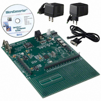
KIT DEV FOR ADUC831 QUICK START
Manufacturer
Analog Devices Inc
Series
QuickStart™ Kitr
Type
MCUr
Datasheet
1.EVAL-ADUC831QSZ.pdf
(76 pages)
Specifications of EVAL-ADUC831QSZ
Contents
Evaluation Board, Power Supply, Cable, Software and Documentation
Silicon Manufacturer
Analog Devices
Core Architecture
8051
Silicon Core Number
ADuC831
Tool / Board Applications
General Purpose MCU, MPU, DSP, DSC
Mcu Supported Families
ADUC8xx
Development Tool Type
Hardware - Eval/Demo Board
Rohs Compliant
Yes
Lead Free Status / RoHS Status
Lead free / RoHS Compliant
For Use With/related Products
ADuC831
Lead Free Status / Rohs Status
Compliant
Other names
EVAL-ADUC831QS
EVAL-ADUC831QS
EVAL-ADUC831QS


The main features of the MicroConverter I
Software Master Mode
The ADuC831 can be used as an I
ing the I
output the data bit by bit. This is referred to as a software master.
Master mode is enabled by setting the I2CM bit in the I2CCON
register.
To transmit data on the SDATA line, MDE must be set to
enable the output driver on the SDATA pin. If MDE is set, then
the SDATA pin will be pulled high or low depending on
whether the MDO bit is set or cleared. MCO controls the
SCLOCK pin and is always configured as an output in master
mode. In master mode the SCLOCK pin will be pulled high or
low depending on the whether MCO is set or cleared.
To receive data, MDE must be cleared to disable the output
driver on SDATA. Software must provide the clocks by toggling
the MCO bit and read the SDATA pin via the MDI bit. If MDE
is cleared MDI can be used to read the SDATA pin. The value of
the SDATA pin is latched into MDI on a rising edge of SCLOCK.
MDI is set if the SDATA pin was high on the last rising edge of
SCLOCK. MDI is cleared if the SDATA pin was low on the last
rising edge of SCLOCK.
Software must control MDO, MCO, and MDE appropriately to
generate the START condition, slave address, acknowledge bits,
data bytes, and STOP conditions appropriately. These functions
are provided in technical note uC001.
Hardware Slave Mode
After reset the ADuC831 defaults to hardware slave mode. The
I
Slave mode is enabled by clearing the I2CM bit in I2CCON.
The ADuC831 has a full hardware slave. In slave mode the I
address is stored in the I2CADD register. Data received or to be
transmitted is stored in the I2CDAT register.
REV. 0
2
C interface is enabled by clearing the SPE bit in SPICON.
• Only two bus lines are required; a serial data line (SDATA)
• An I
• On-Chip filtering rejects <50 ns spikes on the SDATA and
and a serial clock line (SCLOCK).
Because each slave device has a unique 7-bit address, single
master/slave relationships can exist at all times even in
a multislave environment (Figure 34).
the SCLOCK lines to preserve data integrity.
2
2
C peripheral in master mode and writing software to
C master can communicate with multiple slave devices.
Figure 34. Typical I
MASTER
I
2
C
DV
DD
2
C master device by configur-
2
C System
SLAVE #1
SLAVE #2
I
I
2
2
2
C
C
C interface are:
2
C
–41–
Once enabled in I
START condition. If the ADuC831 detects a valid start condi-
tion, followed by a valid address, followed by the R/W bit, the
I2CI interrupt bit will get set by the hardware automatically.
The I
has preconfigured the I
as well as the global interrupt bit EA in the IE SFR.
On the ADuC831 an autoclear of the I2CI bit is implemented
so this bit is cleared automatically on a read or write access to
the I2CDAT SFR.
If for any reason the user tries to clear the interrupt more than
once, i.e., access the data SFR more than once per interrupt
then the I
be reset using the I2CRS bit.
The user can choose to poll the I2CI bit or enable the interrupt.
In the case of the interrupt, the PC counter will vector to
003BH at the end of each complete byte. For the first byte
when the user gets to the I2CI ISR, the 7-bit address and the
R/W bit will appear in the I2CDAT SFR.
The I2CTX bit contains the R/W bit sent from the master. If
I2CTX is set then the master would like to receive a byte.
Thus the slave will transmit data by writing to the I2CDAT
register. If I2CTX is cleared, the master would like to transmit
a byte. Therefore, the slave will receive a serial byte. Software
can interrogate the state of I2CTX to determine whether it
should write to or read from I2CDAT.
Once the ADuC831 has received a valid address, hardware will
hold SCLOCK low until the I2CI bit is cleared by software.
This allows the master to wait for the slave to be ready before
transmitting the clocks for the next byte.
The I2CI interrupt bit will be set every time a complete data
byte is received or transmitted, provided it is followed by a valid
ACK. If the byte is followed by a NACK an interrupt is NOT
generated. The ADuC831 will continue to issue interrupts for
each complete data byte transferred until a STOP condition is
received or the interface is reset.
When a STOP condition is received, the interface will reset to a
state where it is waiting to be addressed (idle). Similarly, if the
interface receives a NACK at the end of a sequence it also returns
to the default idle state. The I2CRS bit can be used to reset the
I
the default idle state.
It should be noted that there is no way (in hardware) to distinguish
between an interrupt generated by a received START + valid
address and an interrupt generated by a received data byte. User
software must be used to distinguish between these interrupts.
2
C interface. This bit can be used to force the interface back to
; Enabling I2C Interrupts for the ADuC831
MOV
SETB EA
MOV
MOV
2
C peripheral will only generate a core interrupt if the user
IEIP2,#01H
2
C controller will halt. The interface will then have to
I2CDAT, A
A, I2CDAT
2
C slave mode the slave controller waits for a
2
C interrupt enable bit in the IEIP2 SFR
; enable I2C interrupt
; I2CI auto cleared
; I2CI auto cleared
ADuC831
Related parts for EVAL-ADUC831QSZ
Image
Part Number
Description
Manufacturer
Datasheet
Request
R


Part Number:
Description:
BOARD EVAL FOR SI270X-A
Manufacturer:
Silicon Laboratories Inc
Datasheet:

Part Number:
Description:
BUCK CONV REF DESIGN KIT IP1201
Manufacturer:
International Rectifier
Datasheet:
Part Number:
Description:
BOARD DEMO SYNC DUAL BUCK CNVTER
Manufacturer:
International Rectifier
Datasheet:
Part Number:
Description:
BOARD DEMO SYNC BUCK CONVETER
Manufacturer:
International Rectifier
Datasheet:

Part Number:
Description:
EVALBOARD/EB Omnidirectional microphone - Analog
Manufacturer:
Analog Devices
Datasheet:
Part Number:
Description:
EVALBOARD/EB Omnidirectional microphone - Analog
Manufacturer:
Analog Devices
Datasheet:


Part Number:
Description:
BOARD EVAL LED DRIVER LT3756
Manufacturer:
Linear Technology
Datasheet:

Part Number:
Description:
BOARD EVAL FOR AD7741/7742
Manufacturer:
Analog Devices Inc
Datasheet:

Part Number:
Description:
±1.7g Dual-Axis IMEMS Accelerometer Evaluation Board
Manufacturer:
Analog Devices Inc
Datasheet:

Part Number:
Description:
IC MULTIPLIER ANALOG 8-SOIC T/R
Manufacturer:
Analog Devices Inc
Datasheet:

Part Number:
Description:
IC ANALOG MULTIPLIER 8-DIP
Manufacturer:
Analog Devices Inc
Datasheet:
Part Number:
Description:
IC ANALOG MULTIPLIER 8-SOIC
Manufacturer:
Analog Devices Inc
Datasheet:
Part Number:
Description:
IC ANALOG MULTIPLIER 8-DIP
Manufacturer:
Analog Devices Inc
Datasheet: