EVAL-ADUC831QSZ Analog Devices Inc, EVAL-ADUC831QSZ Datasheet - Page 58
EVAL-ADUC831QSZ
Manufacturer Part Number
EVAL-ADUC831QSZ
Description
KIT DEV FOR ADUC831 QUICK START
Manufacturer
Analog Devices Inc
Series
QuickStart™ Kitr
Type
MCUr
Datasheet
1.EVAL-ADUC831QSZ.pdf
(76 pages)
Specifications of EVAL-ADUC831QSZ
Contents
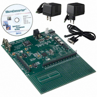
Evaluation Board, Power Supply, Cable, Software and Documentation
Silicon Manufacturer
Analog Devices
Core Architecture
8051
Silicon Core Number
ADuC831
Tool / Board Applications
General Purpose MCU, MPU, DSP, DSC
Mcu Supported Families
ADUC8xx
Development Tool Type
Hardware - Eval/Demo Board
Rohs Compliant
Yes
Lead Free Status / RoHS Status
Lead free / RoHS Compliant
For Use With/related Products
ADuC831
Lead Free Status / Rohs Status
Compliant
Other names
EVAL-ADUC831QS
EVAL-ADUC831QS
EVAL-ADUC831QS


ADuC831
Timer 3 Generated Baud Rates
The high integer dividers in a UART block mean that high speed
baud rates are not always possible using some particular crystals.
For example, using a 12 MHz crystal, a baud rate of 115200 is
not possible. To address this problem, the ADuC831 has added
a dedicated baud rate timer (Timer 3) specifically for generating
highly accurate baud rates.
Timer 3 can be used instead of Timer 1 or Timer 2 for generating
very accurate high speed UART baud rates including 115200
and 230400. Timer 3 also allows a much wider range of baud
rates to be obtained. In fact, every desired bit rate from 12 bit/s
to 393216 bit/s can be generated to within an error of ± 0.8%.
Timer 3 also frees up the other three timers, allowing them to
be used for different applications. A block diagram of Timer 3 is
shown in Figure 54 below.
Two SFRs (T3CON and T3FD) are used to control Timer 3.
T3CON is the baud rate control SFR, allowing Timer 3 to be
used to set up the UART baud rate, and setting up the binary
divider (DIV).
Bit
7
6
5
4
3
2
1
0
FRACTIONAL
DIVIDER
CORE
CLK
Name
T3BAUDEN
DIV2
DIV1
DIV0
Table XXVI. T3CON SFR Bit Designations
Figure 54. Timer 3, UART Baud Rates
(1 + T3FD/64)
2
16
DIV
2
T3 RX/TX
CLOCK
Description
T3UARTBAUD Enable
Set to enable Timer 3 to generate
the baud rate. When set, PCON.7,
T2CON.4 and T2CON.5 are ignored.
Cleared to let the baud rate be
generated as per a standard 8052.
Binary Divider Factor.
DIV2 DIV1 DIV0 Bin Divider
–
–
–
–
RX CLOCK (FIG 53)
0
0
0
0
1
1
1
1
TIMER 1/TIMER 2
1
1
0
0
1
1
0
0
1
1
TX CLOCK (FIG 53)
0
0
TIMER 1/TIMER 2
0
1
0
1
0
1
0
1
T3EN
1
1
1
1
1
1
1
1
RX CLOCK
TX CLOCK
–58–
The appropriate value to write to the DIV2-1-0 bits can be calcu-
lated using the following formula where f
frequency:
Note: The DIV value must be rounded down.
T3FD is the fractional divider ratio required to achieve the
required baud rate. We can calculate the appropriate value for
T3FD using the following formula.
Note: T3FD should be rounded to the nearest integer.
Once the values for DIV and T3FD are calculated the actual
baud rate can be calculated using the following formula.
For example, to get a baud rate of 115200 while operating at
11.0592 MHz:
Therefore, the actual baud rate is 115200 bit/s.
Ideal
Baud
230400 11.0592
115200 11.0592
57600
38400
19200
9600
230400 12
115200 12
57600
38400
19200
9600
230400 14
115200 14
57600
38400
19200
9600
230400 16
115200 16
57600
38400
19200
9600
DIV
T FD
Table XXVII. Commonly Used Baud Rates Using Timer 3
3
=
=
LOG
11.0592
11.0592
11.0592
11.0592
12
12
12
12
14
14
14
14
16
16
16
16
Actual Baud Rate =
Crystal
(
2 11059200
×
(
11059200 32 115200
DIV
T FD
3
=
DIV
0
1
2
3
4
5
0
1
2
3
4
5
0
1
2
3
4
5
1
2
3
3
4
5
log
=
)
/
/
2
(
(
2
DIV
32 Baud Rate
1
×
2
×
log( ) 2
2
×
T3CON
80H
81H
82H
83H
84H
85H
80H
81H
82H
83H
84H
85H
80H
81H
82H
83H
84H
85H
81H
82H
83H
83H
84H
85H
×
115200
×
DIV
f
Baud Rate
CORE
f
CORE
2
×
×
)
(T3FD+ 64)
)
CORE
f
)
–
CORE
/
64
LOG
20H
20H
20H
08H
08H
08H
28H
28H
28H
0EH
0EH
0EH
3AH
3AH
3AH
1BH
1BH
1BH
05H
05H
05H
28H
28H
28H
T3FD
is the crystal
=
32 20
2 1 58 1
=
=
%
Error
.
0.0
0.0
0.0
0.0
0.0
0.0
0.16
0.16
0.16
0.16
0.16
0.16
0.39
0.39
0.39
0.16
0.16
0.16
0.64
0.64
0.64
0.16
0.16
0.16
REV. 0
H
=
Related parts for EVAL-ADUC831QSZ
Image
Part Number
Description
Manufacturer
Datasheet
Request
R


Part Number:
Description:
BOARD EVAL FOR SI270X-A
Manufacturer:
Silicon Laboratories Inc
Datasheet:

Part Number:
Description:
BUCK CONV REF DESIGN KIT IP1201
Manufacturer:
International Rectifier
Datasheet:
Part Number:
Description:
BOARD DEMO SYNC DUAL BUCK CNVTER
Manufacturer:
International Rectifier
Datasheet:
Part Number:
Description:
BOARD DEMO SYNC BUCK CONVETER
Manufacturer:
International Rectifier
Datasheet:

Part Number:
Description:
EVALBOARD/EB Omnidirectional microphone - Analog
Manufacturer:
Analog Devices
Datasheet:
Part Number:
Description:
EVALBOARD/EB Omnidirectional microphone - Analog
Manufacturer:
Analog Devices
Datasheet:


Part Number:
Description:
BOARD EVAL LED DRIVER LT3756
Manufacturer:
Linear Technology
Datasheet:

Part Number:
Description:
BOARD EVAL FOR AD7741/7742
Manufacturer:
Analog Devices Inc
Datasheet:

Part Number:
Description:
±1.7g Dual-Axis IMEMS Accelerometer Evaluation Board
Manufacturer:
Analog Devices Inc
Datasheet:

Part Number:
Description:
IC MULTIPLIER ANALOG 8-SOIC T/R
Manufacturer:
Analog Devices Inc
Datasheet:

Part Number:
Description:
IC ANALOG MULTIPLIER 8-DIP
Manufacturer:
Analog Devices Inc
Datasheet:
Part Number:
Description:
IC ANALOG MULTIPLIER 8-SOIC
Manufacturer:
Analog Devices Inc
Datasheet:
Part Number:
Description:
IC ANALOG MULTIPLIER 8-DIP
Manufacturer:
Analog Devices Inc
Datasheet: