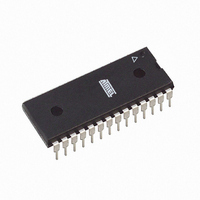
ATTINY48-PU Atmel, ATTINY48-PU Datasheet - Page 209

ATTINY48-PU
Manufacturer Part Number
ATTINY48-PU
Description
MCU AVR 4K ISP FLASH 1.8V 28-DIP
Manufacturer
Atmel
Series
AVR® ATtinyr
Specifications of ATTINY48-PU
Core Processor
AVR
Core Size
8-Bit
Speed
12MHz
Connectivity
I²C, SPI
Peripherals
Brown-out Detect/Reset, POR, WDT
Number Of I /o
24
Program Memory Size
4KB (2K x 16)
Program Memory Type
FLASH
Eeprom Size
64 x 8
Ram Size
256 x 8
Voltage - Supply (vcc/vdd)
1.8 V ~ 5.5 V
Data Converters
A/D 6x10b
Oscillator Type
Internal
Operating Temperature
-40°C ~ 85°C
Package / Case
28-DIP (0.300", 7.62mm)
Processor Series
ATTINY4x
Core
AVR8
Data Bus Width
8 bit
Data Ram Size
256 B
Interface Type
2-Wire/I2S/SPI
Maximum Clock Frequency
12 MHz
Number Of Programmable I/os
28
Number Of Timers
2
Maximum Operating Temperature
+ 85 C
Mounting Style
Through Hole
3rd Party Development Tools
EWAVR, EWAVR-BL
Development Tools By Supplier
ATAVRDRAGON, ATSTK500, ATSTK600, ATAVRISP2, ATAVRONEKIT
Minimum Operating Temperature
- 40 C
On-chip Adc
6-ch x 10-bit
Package
28PDIP
Device Core
AVR
Family Name
ATtiny
Maximum Speed
12 MHz
Operating Supply Voltage
2.5|3.3|5 V
For Use With
ATSTK600 - DEV KIT FOR AVR/AVR32ATAVRDRAGON - KIT DRAGON 32KB FLASH MEM AVRATAVRISP2 - PROGRAMMER AVR IN SYSTEM
Lead Free Status / RoHS Status
Lead free / RoHS Compliant
Available stocks
Company
Part Number
Manufacturer
Quantity
Price
Company:
Part Number:
ATTINY48-PU
Manufacturer:
ATMEL
Quantity:
5 530
Company:
Part Number:
ATTINY48-PU
Manufacturer:
AVX
Quantity:
30 000
- Current page: 209 of 302
- Download datasheet (9Mb)
22.4.2
22.5
8008G–AVR–04/11
System and Reset Characterizations
External Clock Drive
Figure 22-2. External Clock Drive Waveforms
Table 22-2.
Note:
Table 22-3.
Symbol
1/t
t
t
t
t
t
Δ
CLCL
CHCX
CLCX
CLCH
CHCL
Symbol
t
CLCL
V
V
CLCL
t
RST
POT
RST
All DC Characteristics contained in this datasheet are based on simulation and characterization of
other AVR microcontrollers manufactured in the same process technology.
V
Parameter
Oscillator
Frequency
Clock Period
High Time
Low Time
Rise Time
Fall Time
Change in period
from one clock
cycle to the next
Parameter
Power-on Reset Threshold
Voltage (rising)
Power-on Reset Threshold
Voltage (falling)
RESET Pin Threshold
Voltage
Minimum pulse width on
RESET Pin
IL1
External Clock Drive
Reset, Brown-out, and Internal Voltage Characteristics
V
IH1
(2)
V
Min.
250
120
120
CC
0
= 1.8-5.5V
Condition
T
T
V
V
V
A
A
CC
CC
CC
= -40 to +85°C
= -40 to +85°C
Max.
2.0
2.0
= 1.8V
= 3V
= 5V
2
2
Min.
V
166
80
80
CC
0
= 2.7-5.5V
0.2V
Min
Max.
1.6
1.6
6
2
CC
(1)
2000
Typ
700
400
V
Min.
1.5
1.2
83
40
40
CC
0
ATtiny48/88
= 4.5-5.5V
0.9V
Max
Max.
0.5
0.5
12
2
CC
Units
Units
MHz
ns
ns
ns
ns
µs
µs
%
V
V
V
209
Related parts for ATTINY48-PU
Image
Part Number
Description
Manufacturer
Datasheet
Request
R

Part Number:
Description:
Manufacturer:
Atmel Corporation
Datasheet:

Part Number:
Description:
Microcontrollers (MCU) 512B FL 32B SRAM TIMER ATTINY4 12MHz
Manufacturer:
Atmel

Part Number:
Description:
IC MCU AVR 512B FLASH SOT-23-6
Manufacturer:
Atmel
Datasheet:

Part Number:
Description:
IC MCU AVR 512B FLASH SOT-23-6
Manufacturer:
Atmel
Datasheet:

Part Number:
Description:
IC, MCU, 8BIT, 2K FLASH, 20SOIC
Manufacturer:
Atmel
Datasheet:

Part Number:
Description:
IC, MCU, 8BIT, 2K FLASH, 20PDIP
Manufacturer:
Atmel
Datasheet:

Part Number:
Description:
IC, MCU, 8BIT, 8K FLASH, 20PDIP
Manufacturer:
Atmel
Datasheet:

Part Number:
Description:
IC, MCU, 8BIT, 8K FLASH, 20SOIC
Manufacturer:
Atmel
Datasheet:

Part Number:
Description:
DEV KIT FOR AVR/AVR32
Manufacturer:
Atmel
Datasheet:

Part Number:
Description:
INTERVAL AND WIPE/WASH WIPER CONTROL IC WITH DELAY
Manufacturer:
ATMEL Corporation
Datasheet:

Part Number:
Description:
Low-Voltage Voice-Switched IC for Hands-Free Operation
Manufacturer:
ATMEL Corporation
Datasheet:

Part Number:
Description:
MONOLITHIC INTEGRATED FEATUREPHONE CIRCUIT
Manufacturer:
ATMEL Corporation
Datasheet:

Part Number:
Description:
AM-FM Receiver IC U4255BM-M
Manufacturer:
ATMEL Corporation
Datasheet:


