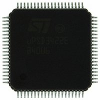
UPSD3422E-40U6 STMicroelectronics, UPSD3422E-40U6 Datasheet - Page 151

UPSD3422E-40U6
Manufacturer Part Number
UPSD3422E-40U6
Description
MCU 8BIT 8032 64KB FLASH 80TQFP
Manufacturer
STMicroelectronics
Series
µPSDr
Datasheet
1.UPSD3422EV-40U6.pdf
(300 pages)
Specifications of UPSD3422E-40U6
Core Processor
8032
Core Size
8-Bit
Speed
40MHz
Connectivity
I²C, IrDA, SPI, UART/USART, USB
Peripherals
LVD, POR, PWM, WDT
Number Of I /o
46
Program Memory Size
80KB (80K x 8)
Program Memory Type
FLASH
Ram Size
4K x 8
Voltage - Supply (vcc/vdd)
3 V ~ 5.5 V
Data Converters
A/D 8x10b
Oscillator Type
Internal
Operating Temperature
-40°C ~ 85°C
Package / Case
80-TQFP, 80-VQFP
For Use With
497-5577 - BOARD EVAL USB POWER SWITCH497-5518 - EVAL BOARD RFID READER
Lead Free Status / RoHS Status
Lead free / RoHS Compliant
Eeprom Size
-
Other names
497-4903
Available stocks
Company
Part Number
Manufacturer
Quantity
Price
Company:
Part Number:
UPSD3422E-40U6
Manufacturer:
STMicroelectronics
Quantity:
10 000
- Current page: 151 of 300
- Download datasheet (3Mb)
UPSD3422, UPSD3433, UPSD3434, UPSD3454
25.1
25.1.1
Figure 48. USB module block diagram
Basic USB concepts
The Universal Serial Bus (USB) is more complex than the standard serial port and requires
familiarity with the specification to fully understand how to use the USB peripheral in the
UPSD34xx. The USB specification is available on the Internet at http://www.usb.org.
Some basic concepts will be presented in this section but knowledge of the USB
specification is required.
In a USB system, there is only one master and the master is the host computer. The host
controls all activity on the bus and devices respond to requests from the host. The only
exception is when a device has been put into a low power suspend mode by the host. In this
case, the device can signal a remote wakeup. Outside of that exception, all activity is
controlled and initiated by the host. The host-centric model versus a peer-to-peer model
provides the best way to develop low cost peripherals by keeping the complex control logic
on the host side. The UPSD34xx is a peripheral (non-host) device.
Communication flow
The USB provides a means for communication between host (client) software and a function
on a USB device. Functions can have different requirements for the communication flow
depending on the client software to the USB function interaction. With USB, the various
communication flows are separated to provide better bus utilization. For example, one
communication flow is used for managing the device while another is for transferring data
related to the operation of the device. Some bus access is used for each communication
flow with each flow terminated at an endpoint on a device. Each endpoint has various
aspects associated with the communication flow. A USB device looks like a collection of
endpoints to the USB system.
D–
D+
USB–
USB+
transceiver
USB
interface
CTRL and data
rngine
Clock
Serial
PLL
3 - 40 MHz
48 MHz
Endpoint0
Endpoint0
Endpoint4
Endpoint4
OUT FIFOs (64 bytes each)
SETUP command
IN FIFOs (64 bytes each)
buffer (8 bytes)
FIFO interface logic
CTRL
CTRL and data
XDATA
CTRL
USB interface
USB SFRs
8032
MCU
AI10488
S
F
R
b
u
s
151/300
Related parts for UPSD3422E-40U6
Image
Part Number
Description
Manufacturer
Datasheet
Request
R

Part Number:
Description:
Fast Turbo 8032 MCU with USB and Programmable Logic
Manufacturer:
STMICROELECTRONICS [STMicroelectronics]
Datasheet:

Part Number:
Description:
MCU 8BIT 8032 64KB FLASH 52TQFP
Manufacturer:
STMicroelectronics
Datasheet:

Part Number:
Description:
STMicroelectronics [RIPPLE-CARRY BINARY COUNTER/DIVIDERS]
Manufacturer:
STMicroelectronics
Datasheet:

Part Number:
Description:
STMicroelectronics [LIQUID-CRYSTAL DISPLAY DRIVERS]
Manufacturer:
STMicroelectronics
Datasheet:

Part Number:
Description:
BOARD EVAL FOR MEMS SENSORS
Manufacturer:
STMicroelectronics
Datasheet:

Part Number:
Description:
NPN TRANSISTOR POWER MODULE
Manufacturer:
STMicroelectronics
Datasheet:

Part Number:
Description:
TURBOSWITCH ULTRA-FAST HIGH VOLTAGE DIODE
Manufacturer:
STMicroelectronics
Datasheet:

Part Number:
Description:
Manufacturer:
STMicroelectronics
Datasheet:

Part Number:
Description:
DIODE / SCR MODULE
Manufacturer:
STMicroelectronics
Datasheet:

Part Number:
Description:
DIODE / SCR MODULE
Manufacturer:
STMicroelectronics
Datasheet:

Part Number:
Description:
Search -----> STE16N100
Manufacturer:
STMicroelectronics
Datasheet:

Part Number:
Description:
Search ---> STE53NA50
Manufacturer:
STMicroelectronics
Datasheet:


