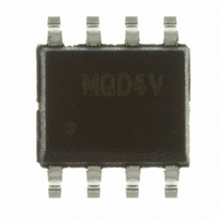
MC9S08QD4VSC Freescale Semiconductor, MC9S08QD4VSC Datasheet - Page 64

MC9S08QD4VSC
Manufacturer Part Number
MC9S08QD4VSC
Description
IC MCU 4K FLASH 256RAM 8-SOIC
Manufacturer
Freescale Semiconductor
Series
HCS08r
Specifications of MC9S08QD4VSC
Core Processor
HCS08
Core Size
8-Bit
Speed
10MHz
Peripherals
LVD, POR, PWM, WDT
Number Of I /o
4
Program Memory Size
4KB (4K x 8)
Program Memory Type
FLASH
Ram Size
256 x 8
Voltage - Supply (vcc/vdd)
2.7 V ~ 5.5 V
Data Converters
A/D 4x10b
Oscillator Type
Internal
Operating Temperature
-40°C ~ 125°C
Package / Case
8-SOIC (3.9mm Width)
Processor Series
S08QD
Core
HCS08
Data Bus Width
8 bit
Data Ram Size
256 B
Interface Type
I2C, SCI, SPI
Maximum Clock Frequency
8 MHz
Number Of Programmable I/os
4
Number Of Timers
3
Operating Supply Voltage
2.7 V to 5.5 V
Maximum Operating Temperature
+ 105 C
Mounting Style
SMD/SMT
3rd Party Development Tools
EWS08
Development Tools By Supplier
DEMO9S08QD4
Minimum Operating Temperature
- 40 C
On-chip Adc
4-ch x 10-bit
Cpu Family
HCS08
Device Core Size
8b
Frequency (max)
8MHz
Total Internal Ram Size
256Byte
# I/os (max)
4
Number Of Timers - General Purpose
3
Operating Supply Voltage (typ)
3.3/5V
Operating Supply Voltage (max)
5.5V
Operating Supply Voltage (min)
2.7V
Instruction Set Architecture
CISC
Operating Temp Range
-40C to 105C
Operating Temperature Classification
Industrial
Mounting
Surface Mount
Pin Count
8
Package Type
SOIC N
For Use With
DEMO9S08QD4 - BOARD DEMO FOR MC9S08QD FAMILY
Lead Free Status / RoHS Status
Lead free / RoHS Compliant
Eeprom Size
-
Connectivity
-
Lead Free Status / Rohs Status
Lead free / RoHS Compliant
Available stocks
Company
Part Number
Manufacturer
Quantity
Price
1
2
Chapter 5 Resets, Interrupts, and General System Control
1
2
3
5.8.8
This high-page register contains status and control bits to support the low voltage detect function, and to
enable the bandgap voltage reference for use by the ADC module. To configure the low voltage detect trip
voltage, see
64
Bit 1 is a reserved bit that must always be written to 0.
This bit can be written only one time after reset. Additional writes are ignored.
Values are shown in this column based on t
value.
The initial RTI timeout period will be up to one 1 kHz clock period less than the time specified.
t
Reset:
LVDACK
ext
RTIS2:RTIS1:RTIS0
Field
LVDF
is the period of the 32 kHz ICS frequency.
7
6
W
R
0:0:0
0:0:1
0:1:0
0:1:1
1:0:0
1:0:1
1:1:0
1:1:1
LVDF
System Power Management Status and Control 1 Register
(SPMSC1)
Table 5-13
Figure 5-10. System Power Management Status and Control 1 Register (SPMSC1)
Low-Voltage Detect Flag — Provided LVDE = 1, this read-only status bit indicates a low-voltage detect event.
Low-Voltage Detect Acknowledge — This write-only bit is used to acknowledge low voltage detection errors
(write 1 to clear LVDF). Reads always return 0.
0
7
= Unimplemented or Reserved
LVDACK
for the LVDV bit description in SPMSC2.
0
0
6
Using Internal 1 kHz Clock Source
Table 5-12. SPMSC1 Register Field Descriptions
MC9S08QD4 Series MCU Data Sheet, Rev. 6
Table 5-11. Real-Time Interrupt Period
LVDIE
RTI
0
5
Disable RTI
128 ms
256 ms
512 ms
1.024 s
= 1 ms. See t
32 ms
64 ms
8 ms
LVDRE
1
4
RTI
2
Description
in the
1 2
Section A.8.1, “Control
LVDSE
3
1
Using 32 kHz ICS Clock Source
LVDE
1
2
2
Period = t
Timing,” for the tolerance of this
Disable RTI
t
t
t
t
t
t
ext
ext
t
ext
ext
ext
ext
ext
× 16384
× 32768
× 1024
× 2048
× 4096
× 8192
× 256
Freescale Semiconductor
1
0
0
ext
1
3
BGBE
0
0


