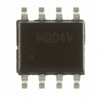
MC9S08QD4VSC Freescale Semiconductor, MC9S08QD4VSC Datasheet - Page 96

MC9S08QD4VSC
Manufacturer Part Number
MC9S08QD4VSC
Description
IC MCU 4K FLASH 256RAM 8-SOIC
Manufacturer
Freescale Semiconductor
Series
HCS08r
Specifications of MC9S08QD4VSC
Core Processor
HCS08
Core Size
8-Bit
Speed
10MHz
Peripherals
LVD, POR, PWM, WDT
Number Of I /o
4
Program Memory Size
4KB (4K x 8)
Program Memory Type
FLASH
Ram Size
256 x 8
Voltage - Supply (vcc/vdd)
2.7 V ~ 5.5 V
Data Converters
A/D 4x10b
Oscillator Type
Internal
Operating Temperature
-40°C ~ 125°C
Package / Case
8-SOIC (3.9mm Width)
Processor Series
S08QD
Core
HCS08
Data Bus Width
8 bit
Data Ram Size
256 B
Interface Type
I2C, SCI, SPI
Maximum Clock Frequency
8 MHz
Number Of Programmable I/os
4
Number Of Timers
3
Operating Supply Voltage
2.7 V to 5.5 V
Maximum Operating Temperature
+ 105 C
Mounting Style
SMD/SMT
3rd Party Development Tools
EWS08
Development Tools By Supplier
DEMO9S08QD4
Minimum Operating Temperature
- 40 C
On-chip Adc
4-ch x 10-bit
Cpu Family
HCS08
Device Core Size
8b
Frequency (max)
8MHz
Total Internal Ram Size
256Byte
# I/os (max)
4
Number Of Timers - General Purpose
3
Operating Supply Voltage (typ)
3.3/5V
Operating Supply Voltage (max)
5.5V
Operating Supply Voltage (min)
2.7V
Instruction Set Architecture
CISC
Operating Temp Range
-40C to 105C
Operating Temperature Classification
Industrial
Mounting
Surface Mount
Pin Count
8
Package Type
SOIC N
For Use With
DEMO9S08QD4 - BOARD DEMO FOR MC9S08QD FAMILY
Lead Free Status / RoHS Status
Lead free / RoHS Compliant
Eeprom Size
-
Connectivity
-
Lead Free Status / Rohs Status
Lead free / RoHS Compliant
Available stocks
Company
Part Number
Manufacturer
Quantity
Price
Chapter 8 Analog-to-Digital Converter (ADC10V1)
The RTI can be configured to cause a hardware trigger in MCU run, wait, and stop3.
8.1.1.4
The ADC on MC9S08QD4 contains only one analog pin enable register, APCTL1.
8.1.1.5
To use the on-chip temperature sensor, the user must perform the following:
Equation 8-1
Temp = 25°C, using the ADC at f
0.0017 is the uncalibrated voltage versus temperature slope in V/°C. Uncalibrated accuracy of the
temperature sensor is approximately
To improve accuracy the user must calibrate the bandgap voltage reference and temperature sensor.
Calibrating at 25°C will improve accuracy to
Calibration at 3 points, -40°C, 25°C and 105°C will improve accuracy to
been completed, the user will need to calculate the slope for both hot and cold. In application code, the
user would then calculate the temperature using
temperature is above or below 25°C. Once determined if the temperature is above or below 25°C, the user
can recalculate the temperature using the hot or cold slope value obtained during calibration.
8.1.1.6
The ADC is capable of running in stop3 mode but requires LVDSE in SPMSC1 to be set.
96
•
•
•
Configure ADC for long sample with a maximum of 1 MHz clock
Convert the bandgap voltage reference channel (AD27)
— By converting the digital value of the bandgap voltage reference channel using the value of
Convert the temperature sensor channel (AD26)
— By using the calculated value of V
V
Characteristics”.
BG
Analog Pin Enables
Temperature Sensor
provides an approximate transfer function of the on-chip temperature sensor for V
Low-Power Mode Operation
the user can determine V
TempC = 25 – ((V
MC9S08QD4 Series MCU Data Sheet, Rev. 6
ADCK
±
12°C, using
= 1.0 MHz and configured for long sample.
DD
. For value of bandgap voltage, see
TEMP
±
DD
4.5°C.
Equation 8-1
, convert the digital value of AD26 into a voltage,
– 1.3894) / ( 0.0033))
Equation
8-1.
as detailed above and then determine if the
±
2.5°C. Once calibration has
Appendix A.5, “DC
Freescale Semiconductor
DD
Eqn. 8-1
= 3.0V,
V
TEMP


