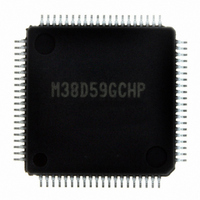
M38D59GCHP#U0 Renesas Electronics America, M38D59GCHP#U0 Datasheet - Page 57

M38D59GCHP#U0
Manufacturer Part Number
M38D59GCHP#U0
Description
IC 740/38D5 MCU QZ-ROM 80LQFP
Manufacturer
Renesas Electronics America
Series
740/38000r
Datasheet
1.M38D58G8FPU0.pdf
(144 pages)
Specifications of M38D59GCHP#U0
Core Processor
740
Core Size
8-Bit
Speed
12.5MHz
Connectivity
SIO, UART/USART
Peripherals
LCD, LED, PWM, WDT
Number Of I /o
59
Program Memory Size
48KB (48K x 8)
Program Memory Type
QzROM
Ram Size
2K x 8
Voltage - Supply (vcc/vdd)
1.8 V ~ 5.5 V
Data Converters
A/D 8x10b
Oscillator Type
Internal
Operating Temperature
-20°C ~ 85°C
Package / Case
80-LQFP
Lead Free Status / RoHS Status
Lead free / RoHS Compliant
Eeprom Size
-
Available stocks
Company
Part Number
Manufacturer
Quantity
Price
38D5 Group
Rev.3.04
REJ03B0158-0304
• LCD Display RAM
The 36-byte area of address 0840
RAM for the LCD display. When “1” is written to these
addresses, the corresponding segments of the LCD display panel
are turned on.
The LCDCK timing frequency (LCD drive timing) is generated
internally and the frame frequency can be determined with the
following equation;
f(LCDCK)=
Frame frequency=
Fig. 46 LCD display RAM map
Address
0840
0841
0842
0843
0844
0845
0846
0847
0848
0849
084A
084B
084C
084D
084E
084F
0850
0851
0852
0853
0854
0855
0856
0857
0858
0859
085A
085B
085C
085D
085E
085F
0860
0861
0862
0863
Bits
16
16
16
16
16
16
16
16
16
16
16
16
16
16
16
16
16
16
16
16
16
16
16
16
16
16
16
16
16
16
16
16
16
16
16
16
May 20, 2008 Page 55 of 134
(frequency of count source for LCDCK)
Not used
(This area can be used
as normal RAM.)
7
(divider division ratio for LCD)
f(LCDCK)
duty ratio
6
at 4COM × 36SEG
5
16
4
to 0863
COM
3
16
3
COM
is the designated
SEG
SEG
SEG
SEG
SEG
SEG
SEG
SEG
SEG
SEG
SEG
SEG
SEG
SEG
SEG
SEG
SEG
SEG
SEG
SEG
SEG
SEG
SEG
SEG
SEG
SEG
SEG
SEG
SEG
SEG
SEG
SEG
SEG
SEG
SEG
SEG
2
2
COM
0
1
2
3
4
5
6
7
8
9
10
11
12
13
14
15
16
17
18
19
20
21
22
23
24
25
26
27
28
29
30
31
32
33
34
35
1
1
COM
0
0
<Notes>
(1) Executing STP Instruction
Executing the STP instruction sets the LCD enable bit (bit 4 of
LCD mode register1 (address 0013
turns off. To turn the LCD panel on after returning from stop
mode, set the LCD enable bit to “1”.
(2) V
To use the LCD drive control circuit while V
voltage equal to V
write “1” to the V
(address 0014
Address
0840
0841
0842
0843
0844
0845
0846
0847
0848
0849
084A
084B
084C
084D
084E
084F
0850
0851
0852
0853
0854
0855
0856
0857
0858
0859
085A
085B
085C
085D
085E
085F
0860
0861
0862
0863
L3
Bits
16
16
16
16
16
16
16
16
16
16
16
16
16
16
16
16
16
16
16
16
16
16
16
16
16
16
16
16
16
16
16
16
16
16
16
16
Pin
COM
16
7
)).
7
L3
COM
CC
connection bit (bit 1 of LCD mode register 2
6
, apply the V
6
at 8COM × 32SEG
Not used
(This area can be used as normal RAM.)
COM
5
5
COM
SEG
SEG
SEG
SEG
SEG
SEG
SEG
SEG
SEG
SEG
SEG
SEG
SEG
SEG
SEG
SEG
SEG
SEG
SEG
SEG
SEG
SEG
SEG
SEG
SEG
SEG
SEG
SEG
SEG
SEG
SEG
SEG
4
CC
4
16
COM
10
11
12
13
14
15
16
17
18
19
20
21
22
23
24
25
26
27
28
29
30
31
)) to “0” and the LCD panel
0
1
2
3
4
5
6
7
8
9
voltage to the V
3
3
COM
2
2
COM
L3
1
is set to the
1
L3
COM
pin and
0
0


