DF2161BVTE10 Renesas Electronics America, DF2161BVTE10 Datasheet - Page 347
DF2161BVTE10
Manufacturer Part Number
DF2161BVTE10
Description
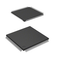
MCU 3V 128K 144-TQFP
Manufacturer
Renesas Electronics America
Series
H8® H8S/2100r
Datasheet
1.DF2160BVT10V.pdf
(847 pages)
Specifications of DF2161BVTE10
Core Processor
H8S/2000
Core Size
16-Bit
Speed
10MHz
Connectivity
Host Interface (LPC), I²C, IrDA, SCI, X-Bus
Peripherals
PWM, WDT
Number Of I /o
114
Program Memory Size
128KB (128K x 8)
Program Memory Type
FLASH
Ram Size
4K x 8
Voltage - Supply (vcc/vdd)
2.7 V ~ 3.6 V
Data Converters
A/D 8x10b; D/A 2x8b
Oscillator Type
Internal
Operating Temperature
-20°C ~ 75°C
Package / Case
144-TQFP, 144-VQFP
Lead Free Status / RoHS Status
Contains lead / RoHS non-compliant
Eeprom Size
-
Other names
HD64F2161BVTE10
HD64F2161BVTE10
HD64F2161BVTE10


12.3.1
Each TCNT is an 8-bit readable/writable up-counter. TCNT_0 and TCNT_1 comprise a single 16-
bit register, so they can be accessed together by word access. The clock source is selected by the
CKS2 to CKS0 bits in TCR. TCNT can be cleared by an external reset input signal, compare-
match A signal or compare-match B signal. The method of clearing can be selected by the CCLR1
and CCLR0 bits in TCR. When TCNT overflows (changes from H'FF to H'00), the OVF bit in
TCSR is set to 1. TCNT is initialized to H'00.
12.3.2
TCORA is an 8-bit readable/writable register. TCORA_0 and TCORA_1 comprise a single 16-bit
register, so they can be accessed together by word access. TCORA is continually compared with
the value in TCNT. When a match is detected, the corresponding compare-match flag A (CMFA)
in TCSR is set to 1. Note however that comparison is disabled during the T2 state of a TCORA
write cycle. The timer output from the TMO pin can be freely controlled by these compare-match
A signals and the settings of output select bits OS1 and OS0 in TCSR. TCORA is initialized to
H'FF.
12.3.3
TCORB is an 8-bit readable/writable register. TCORB_0 and TCORB_1 comprise a single 16-bit
register, so they can be accessed together by word access. TCORB is continually compared with
the value in TCNT. When a match is detected, the corresponding compare-match flag B (CMFB)
in TCSR is set to 1. Note however that comparison is disabled during the T2 state of a TCORB
write cycle. The timer output from the TMO pin can be freely controlled by these compare-match
B signals and the settings of output select bits OS3 and OS2 in TCSR. TCORB is initialized to
H'FF.
12.3.4
TCR selects the TCNT clock source and the condition by which TCNT is cleared, and
enables/disables interrupt requests.
Timer Counter (TCNT)
Time Constant Register A (TCORA)
Time Constant Register B (TCORB)
Timer Control Register (TCR)
Rev. 3.00 Mar 21, 2006 page 291 of 788
Section 12 8-Bit Timer (TMR)
REJ09B0300-0300
Related parts for DF2161BVTE10
Image
Part Number
Description
Manufacturer
Datasheet
Request
R

Part Number:
Description:
KIT STARTER FOR M16C/29
Manufacturer:
Renesas Electronics America
Datasheet:

Part Number:
Description:
KIT STARTER FOR R8C/2D
Manufacturer:
Renesas Electronics America
Datasheet:

Part Number:
Description:
R0K33062P STARTER KIT
Manufacturer:
Renesas Electronics America
Datasheet:

Part Number:
Description:
KIT STARTER FOR R8C/23 E8A
Manufacturer:
Renesas Electronics America
Datasheet:

Part Number:
Description:
KIT STARTER FOR R8C/25
Manufacturer:
Renesas Electronics America
Datasheet:

Part Number:
Description:
KIT STARTER H8S2456 SHARPE DSPLY
Manufacturer:
Renesas Electronics America
Datasheet:

Part Number:
Description:
KIT STARTER FOR R8C38C
Manufacturer:
Renesas Electronics America
Datasheet:

Part Number:
Description:
KIT STARTER FOR R8C35C
Manufacturer:
Renesas Electronics America
Datasheet:

Part Number:
Description:
KIT STARTER FOR R8CL3AC+LCD APPS
Manufacturer:
Renesas Electronics America
Datasheet:
Part Number:
Description:
KIT STARTER FOR RX610
Manufacturer:
Renesas Electronics America
Datasheet:

Part Number:
Description:
KIT STARTER FOR R32C/118
Manufacturer:
Renesas Electronics America
Datasheet:

Part Number:
Description:
KIT DEV RSK-R8C/26-29
Manufacturer:
Renesas Electronics America
Datasheet:

Part Number:
Description:
KIT STARTER FOR SH7124
Manufacturer:
Renesas Electronics America
Datasheet:

Part Number:
Description:
KIT STARTER FOR H8SX/1622
Manufacturer:
Renesas Electronics America
Datasheet:

Part Number:
Description:
KIT DEV FOR SH7203
Manufacturer:
Renesas Electronics America
Datasheet: