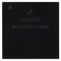
MCF5280CVM66 Freescale Semiconductor, MCF5280CVM66 Datasheet - Page 147

MCF5280CVM66
Manufacturer Part Number
MCF5280CVM66
Description
IC MPU 32BIT COLDF 256-MAPBGA
Manufacturer
Freescale Semiconductor
Series
MCF528xr
Datasheet
1.MCF5216CVM66J.pdf
(766 pages)
Specifications of MCF5280CVM66
Core Processor
Coldfire V2
Core Size
32-Bit
Speed
66MHz
Connectivity
CAN, EBI/EMI, Ethernet, I²C, SPI, UART/USART
Peripherals
DMA, LVD, POR, PWM, WDT
Number Of I /o
142
Program Memory Type
ROMless
Ram Size
64K x 8
Voltage - Supply (vcc/vdd)
2.7 V ~ 3.6 V
Data Converters
A/D 8x10b
Oscillator Type
External
Operating Temperature
-40°C ~ 85°C
Package / Case
256-MAPBGA
Controller Family/series
ColdFire
No. Of I/o's
150
Program Memory Size
2KB
Ram Memory Size
64KB
Cpu Speed
66.67MHz
Embedded Interface Type
CAN, I2C, SPI, UART
No. Of Pwm Channels
8
Rohs Compliant
Yes
Lead Free Status / RoHS Status
Lead free / RoHS Compliant
Eeprom Size
-
Program Memory Size
-
Available stocks
Company
Part Number
Manufacturer
Quantity
Price
Company:
Part Number:
MCF5280CVM66
Manufacturer:
FREESCAL
Quantity:
151
Company:
Part Number:
MCF5280CVM66
Manufacturer:
Freescale Semiconductor
Quantity:
10 000
Company:
Part Number:
MCF5280CVM66J
Manufacturer:
Freescale Semiconductor
Quantity:
10 000
Company:
Part Number:
MCF5280CVM66L
Manufacturer:
FREESCAL
Quantity:
151
- Current page: 147 of 766
- Download datasheet (9Mb)
7.3.2.21 Queued Analog-to-Digital Converter (QADC)
Setting the queued analog-to-digital converter (QADC) stop bit (QSTOP) will disable the QADC.
The QADC is unaffected by either wait or doze mode and may generate an interrupt to exit these modes.
Low-power stop mode (or setting the QSTOP bit), immediately freezes operation, register values, state
machines, and external pins. This stops the clock signals to the digital electronics of the module and
eliminates the quiescent current draw of the analog electronics. Any conversion sequences in progress are
stopped. Exit from low-power stop mode (or clearing the QSTOP bit), returns the QADC to operation from
the state prior to stop mode entry, but any conversions in progress are undefined and the QADC requires
recovery time to stabilize the analog circuits before new conversions can be performed.
7.3.2.22 General Purpose Timers (GPTA and GPTB)
When not stopped, the General Purpose Timers may generate an interrupt to exit the low-power modes.
Clearing the timer enable bit (TE) in the GPT system control register 1 (GPTSCR1) or the pulse
accumulator enable bit (PAE) in the GPT pulse accumulator control register (GPTPACTL) disables timer
functions. Timer and pulse accumulator registers are still accessible by the CPU and BDM interface, but
the remaining functions of the timer are disabled.
The timer is unaffected by either the wait or doze modes and may generate an interrupt to exit these modes.
In stop mode, the General Purpose Timers stop immediately and freeze their operation, register values,
state machines, and external pins. Upon exiting stop mode, the timer will resume operation unless stop
mode was exited by reset.
7.3.2.23 FlexCAN
When enabled, the FlexCAN module is capable of generating interrupts and bringing the device out of a
low-power mode. The module has 35 interrupt sources (32 sources due to message buffers and 3 sources
due to Bus-off, Error and Wake-up).
When in stop mode, a recessive to dominant transition on the CAN bus causes the WAKE-INT bit in the
error & status register to be set. This event can cause a CPU interrupt if the WAKE-MASK bit in module
configuration register (MCR) is set.
When setting stop mode in the FlexCAN (by setting the MCR[STOP] bit), the FlexCAN checks for the
CAN bus to be either idle or waits for the third bit of intermission and checks to see if it is recessive. When
this condition exists, the FlexCAN waits for all internal activity other than in the CAN bus interface to
complete and then the following occurs:
Exiting stop mode is done in one of the following ways:
Freescale Semiconductor
•
•
•
•
•
•
The FlexCAN shuts down its clocks, stopping most of the internal circuits, to achieve maximum
possible power saving.
The internal bus interface logic continues operation, enabling CPU to access the MCR register.
The FlexCAN ignores its Rx input pin, and drives its Tx pins as recessive.
register are set.
Reset the FlexCAN (either by hard reset or by asserting the SOFT_RST bit in MCR).
Clearing the STOP bit in the MCR.
FlexCAN loses synchronization with the CAN bus, and STOP_ACK and NOT_RDY bits in MCR
MCF5282 and MCF5216 ColdFire Microcontroller User’s Manual, Rev. 3
Power Management
7-11
Related parts for MCF5280CVM66
Image
Part Number
Description
Manufacturer
Datasheet
Request
R
Part Number:
Description:
Manufacturer:
Freescale Semiconductor, Inc
Datasheet:
Part Number:
Description:
Manufacturer:
Freescale Semiconductor, Inc
Datasheet:
Part Number:
Description:
Manufacturer:
Freescale Semiconductor, Inc
Datasheet:
Part Number:
Description:
Manufacturer:
Freescale Semiconductor, Inc
Datasheet:
Part Number:
Description:
Manufacturer:
Freescale Semiconductor, Inc
Datasheet:
Part Number:
Description:
Manufacturer:
Freescale Semiconductor, Inc
Datasheet:
Part Number:
Description:
Manufacturer:
Freescale Semiconductor, Inc
Datasheet:
Part Number:
Description:
Manufacturer:
Freescale Semiconductor, Inc
Datasheet:
Part Number:
Description:
Manufacturer:
Freescale Semiconductor, Inc
Datasheet:
Part Number:
Description:
Manufacturer:
Freescale Semiconductor, Inc
Datasheet:
Part Number:
Description:
Manufacturer:
Freescale Semiconductor, Inc
Datasheet:
Part Number:
Description:
Manufacturer:
Freescale Semiconductor, Inc
Datasheet:
Part Number:
Description:
Manufacturer:
Freescale Semiconductor, Inc
Datasheet:
Part Number:
Description:
Manufacturer:
Freescale Semiconductor, Inc
Datasheet:
Part Number:
Description:
Manufacturer:
Freescale Semiconductor, Inc
Datasheet:


