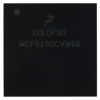
MCF5280CVM66 Freescale Semiconductor, MCF5280CVM66 Datasheet - Page 750

MCF5280CVM66
Manufacturer Part Number
MCF5280CVM66
Description
IC MPU 32BIT COLDF 256-MAPBGA
Manufacturer
Freescale Semiconductor
Series
MCF528xr
Datasheet
1.MCF5216CVM66J.pdf
(766 pages)
Specifications of MCF5280CVM66
Core Processor
Coldfire V2
Core Size
32-Bit
Speed
66MHz
Connectivity
CAN, EBI/EMI, Ethernet, I²C, SPI, UART/USART
Peripherals
DMA, LVD, POR, PWM, WDT
Number Of I /o
142
Program Memory Type
ROMless
Ram Size
64K x 8
Voltage - Supply (vcc/vdd)
2.7 V ~ 3.6 V
Data Converters
A/D 8x10b
Oscillator Type
External
Operating Temperature
-40°C ~ 85°C
Package / Case
256-MAPBGA
Controller Family/series
ColdFire
No. Of I/o's
150
Program Memory Size
2KB
Ram Memory Size
64KB
Cpu Speed
66.67MHz
Embedded Interface Type
CAN, I2C, SPI, UART
No. Of Pwm Channels
8
Rohs Compliant
Yes
Lead Free Status / RoHS Status
Lead free / RoHS Compliant
Eeprom Size
-
Program Memory Size
-
Available stocks
Company
Part Number
Manufacturer
Quantity
Price
Company:
Part Number:
MCF5280CVM66
Manufacturer:
FREESCAL
Quantity:
151
Company:
Part Number:
MCF5280CVM66
Manufacturer:
Freescale Semiconductor
Quantity:
10 000
Company:
Part Number:
MCF5280CVM66J
Manufacturer:
Freescale Semiconductor
Quantity:
10 000
Company:
Part Number:
MCF5280CVM66L
Manufacturer:
FREESCAL
Quantity:
151
- Current page: 750 of 766
- Download datasheet (9Mb)
Bus off interrupt (BOFFINT) 25-27
BUSY 25-11
BYPASS instruction 31-9
C
Cache
Channel flags 20-21
Chip configuration module
Chip select module
CLAMP 31-9
Index-2
SACU 8-11
block diagram 4-2
coherency 4-8
fill buffer 4-2
invalidation 4-8
miss fetch algorithm 4-9
organization 4-1
registers
SRAM interaction 4-7
block diagram 27-2
boot device selection 27-9
chip mode selection 27-8
chip select 27-10
clock mode selection 27-9
features 27-1
interrupts 27-10
memory map 27-3
operation
output pad strength 27-9
programming model 27-3
registers
reset configuration 27-7
single-chip mode 27-1
8-, 16-, and 32-bit port sizing 12-3
memory map 12-4
operation
overview 12-1
registers
access control 0–1 (ACRn) 2-7
control (CACR) 2-7
low-power modes 7-9
master mode 27-1
chip configuration (CCR) 27-4
chip identification (CIR) 27-6
reset configuration register (RCON) 27-5
external boot 12-4
general 12-3
low-power modes 7-7
port sizing 12-3
address (CSARn) 12-6
control (CSCRn) 12-7
mask (CSMRn) 12-6
,
4-9
,
4-3
MCF5282 and MCF5216 ColdFire Microcontroller User’s Manual, Rev. 3
,
4-6
Clock module
ColdFire Core
ColdFire Flash module
block diagram 9-2
features 9-1
memory map 9-5
operation
PLL
registers
system clock
branch instruction execution times 2-32
instruction set summary
block diagram 6-2
configuration field 6-5
electrical characteristics
features 6-1
interrupts 6-23
memory map 6-4
operation
1-1 PLL mode 9-1
during reset 9-11
external clock mode 9-1
low-power modes 7-10
normal PLL mode 9-1
charge pump/loop filter 9-12
lock detection 9-13
loss-of-clock
loss-of-lock
multiplication factor divider (MFD) 9-13
operation 9-11
phase and frequency detector (PFD) 9-12
voltage control output (VCO) 9-13
synthesizer control (SYNCR) 9-6
synthesizer status (SYNSR) 9-8
generation 9-11
modes 9-10
MOVE instruction executino times
MOVE instruction execution times 2-26
timing assumptions 2-25
module life 33-11
program and erase 33-10
low-power modes 7-7
master mode 6-22
program and erase 6-17
alternate clock selection 9-15
detection 9-15
reset 9-15
stop mode 9-16
conditions 9-14
reset 9-15
MOVE long execution times 2-27
MOVE byte and word execution times table 3-9 2-27
misaligned operand references table 3-8 2-26
,
6-7
,
7-13
,
,
9-2
6-18
,
9-13
Freescale Semiconductor
Related parts for MCF5280CVM66
Image
Part Number
Description
Manufacturer
Datasheet
Request
R
Part Number:
Description:
Manufacturer:
Freescale Semiconductor, Inc
Datasheet:
Part Number:
Description:
Manufacturer:
Freescale Semiconductor, Inc
Datasheet:
Part Number:
Description:
Manufacturer:
Freescale Semiconductor, Inc
Datasheet:
Part Number:
Description:
Manufacturer:
Freescale Semiconductor, Inc
Datasheet:
Part Number:
Description:
Manufacturer:
Freescale Semiconductor, Inc
Datasheet:
Part Number:
Description:
Manufacturer:
Freescale Semiconductor, Inc
Datasheet:
Part Number:
Description:
Manufacturer:
Freescale Semiconductor, Inc
Datasheet:
Part Number:
Description:
Manufacturer:
Freescale Semiconductor, Inc
Datasheet:
Part Number:
Description:
Manufacturer:
Freescale Semiconductor, Inc
Datasheet:
Part Number:
Description:
Manufacturer:
Freescale Semiconductor, Inc
Datasheet:
Part Number:
Description:
Manufacturer:
Freescale Semiconductor, Inc
Datasheet:
Part Number:
Description:
Manufacturer:
Freescale Semiconductor, Inc
Datasheet:
Part Number:
Description:
Manufacturer:
Freescale Semiconductor, Inc
Datasheet:
Part Number:
Description:
Manufacturer:
Freescale Semiconductor, Inc
Datasheet:
Part Number:
Description:
Manufacturer:
Freescale Semiconductor, Inc
Datasheet:


