EVAL-ADAU1761Z Analog Devices Inc, EVAL-ADAU1761Z Datasheet - Page 27
EVAL-ADAU1761Z
Manufacturer Part Number
EVAL-ADAU1761Z
Description
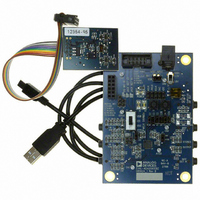
Eval Board For ADAU1761
Manufacturer
Analog Devices Inc
Series
SigmaDSP®r
Specifications of EVAL-ADAU1761Z
Main Purpose
Audio, CODEC
Embedded
Yes, DSP
Utilized Ic / Part
ADAU1761
Primary Attributes
Stereo, 24-Bit, 8 ~ 96 kHz Sampling Rate, GUI Tool
Secondary Attributes
I²C and GPIO Interfaces, 2 Differential and 1 Stereo Single-Ended Analog Inputs and Outputs
Silicon Manufacturer
Analog Devices
Core Architecture
SigmaDSP
Silicon Core Number
ADAU1761
Silicon Family Name
SigmaDSP
Application Sub Type
Audio
Lead Free Status / RoHS Status
Lead free / RoHS Compliant
Available stocks
Company
Part Number
Manufacturer
Quantity
Price
Company:

Part Number:
EVAL-ADAU1761Z
Manufacturer:
Analog Devices Inc
Quantity:
135


SAMPLING RATES
The ADCs, DACs, and serial port share a common sampling
rate that is set in Register R17 (Converter Control 0 register,
Address 0x4017). The CONVSR[2:0] bits set the sampling rate
as a ratio of the base sampling frequency. The DSP sampling
rate is set in Register R57 (DSP sampling rate setting register,
Address 0x40EB) using the DSPSR[3:0] bits, and the serial port
sampling rate is set in Register R64 (serial port sampling rate
register, Address 0x40F8) using the SPSR[2:0] bits.
It is recommended that the sampling rates for the converters,
serial ports, and DSP be set to the same value, unless appropriate
compensation filtering is done within the DSP. Table 13 and
Table 14 list the sampling rate divisions for common base
sampling rates.
Table 13. 48 kHz Base Sampling Rate Divisions
Base Sampling
Frequency
f
Table 14. 44.1 kHz Base Sampling Rate Divisions
Base Sampling
Frequency
f
Table 15. PLL Control Register (Register R1, Address 0x4002)
Bits
[47:32]
[31:16]
[14:11]
S
S
= 48 kHz
= 44.1 kHz
Bit Name
M[15:0]
N[15:0]
R[3:0]
Sampling Rate Scaling
f
f
f
f
f
f
f
Sampling Rate Scaling
f
f
f
f
f
f
f
S
S
S
S
S
S
S
S
S
S
S
S
S
S
/1
/6
/4
/3
/2
/1.5
/0.5
/1
/6
/4
/3
/2
/1.5
/0.5
Description
Denominator of the fractional PLL: 16-bit binary number
0x00FD: M = 253 (default)
Numerator of the fractional PLL: 16-bit binary number
0x000C: N = 12 (default)
Integer part of PLL: four bits, only values 2 to 8 are valid
0010: R = 2 (default)
0011: R = 3
0100: R = 4
0101: R = 5
0110: R = 6
0111: R = 7
1000: R = 8
Sampling Rate
48 kHz
8 kHz
12 kHz
16 kHz
24 kHz
32 kHz
96 kHz
Sampling Rate
44.1 kHz
7.35 kHz
11.025 kHz
14.7 kHz
22.05 kHz
29.4 kHz
88.2 kHz
Rev. C | Page 27 of 92
PLL
The PLL uses the MCLK as a reference to generate the core
clock. PLL settings are set in Register R1 (PLL control register,
Address 0x4002). Depending on the MCLK frequency, the PLL
must be set for either integer or fractional mode. The PLL can
accept input frequencies in the range of 8 MHz to 27 MHz.
All six bytes in the PLL control register must be written with a
single continuous write to the control port.
Integer Mode
Integer mode is used when the MCLK is an integer (R) multiple
of the PLL output (1024 × f
For example, if MCLK = 12.288 MHz and f
In integer mode, the values set for N and M are ignored.
Fractional Mode
Fractional mode is used when the MCLK is a fractional
(R + (N/M)) multiple of the PLL output.
For example, if MCLK = 12 MHz and f
Common fractional PLL parameter settings for 44.1 kHz and
48 kHz sampling rates can be found in Table 16 and Table 17.
The PLL outputs a clock in the range of 41 MHz to 54 MHz,
which should be taken into account when calculating PLL
values and MCLK frequencies.
PLL required output = 1024 × 48 kHz = 49.152 MHz
R = 49.152 MHz/12.288 MHz = 4
PLL required output = 1024 × 48 kHz = 49.152 MHz
R + (N/M) = 49.152 MHz/12 MHz = 4 + (12/125)
MCLK
Figure 31. PLL Block Diagram
÷ X
S
).
× (R + N/M)
S
= 48 kHz, then
CLOCK DIVIDER
S
TO PLL
= 48 kHz, then
ADAU1761
Related parts for EVAL-ADAU1761Z
Image
Part Number
Description
Manufacturer
Datasheet
Request
R


Part Number:
Description:
BOARD EVAL FOR SI270X-A
Manufacturer:
Silicon Laboratories Inc
Datasheet:

Part Number:
Description:
BUCK CONV REF DESIGN KIT IP1201
Manufacturer:
International Rectifier
Datasheet:
Part Number:
Description:
BOARD DEMO SYNC DUAL BUCK CNVTER
Manufacturer:
International Rectifier
Datasheet:
Part Number:
Description:
BOARD DEMO SYNC BUCK CONVETER
Manufacturer:
International Rectifier
Datasheet:

Part Number:
Description:
EVALBOARD/EB Omnidirectional microphone - Analog
Manufacturer:
Analog Devices
Datasheet:
Part Number:
Description:
EVALBOARD/EB Omnidirectional microphone - Analog
Manufacturer:
Analog Devices
Datasheet:


Part Number:
Description:
BOARD EVAL LED DRIVER LT3756
Manufacturer:
Linear Technology
Datasheet:

Part Number:
Description:
BOARD EVAL FOR AD7741/7742
Manufacturer:
Analog Devices Inc
Datasheet:

Part Number:
Description:
±1.7g Dual-Axis IMEMS Accelerometer Evaluation Board
Manufacturer:
Analog Devices Inc
Datasheet:

Part Number:
Description:
IC MULTIPLIER ANALOG 8-SOIC T/R
Manufacturer:
Analog Devices Inc
Datasheet:

Part Number:
Description:
IC ANALOG MULTIPLIER 8-DIP
Manufacturer:
Analog Devices Inc
Datasheet:
Part Number:
Description:
IC ANALOG MULTIPLIER 8-SOIC
Manufacturer:
Analog Devices Inc
Datasheet:
Part Number:
Description:
IC ANALOG MULTIPLIER 8-DIP
Manufacturer:
Analog Devices Inc
Datasheet: