EVAL-ADAU1761Z Analog Devices Inc, EVAL-ADAU1761Z Datasheet - Page 33
EVAL-ADAU1761Z
Manufacturer Part Number
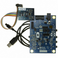
EVAL-ADAU1761Z
Description
Eval Board For ADAU1761
Manufacturer
Analog Devices Inc
Series
SigmaDSP®r
Specifications of EVAL-ADAU1761Z
Main Purpose
Audio, CODEC
Embedded
Yes, DSP
Utilized Ic / Part
ADAU1761
Primary Attributes
Stereo, 24-Bit, 8 ~ 96 kHz Sampling Rate, GUI Tool
Secondary Attributes
I²C and GPIO Interfaces, 2 Differential and 1 Stereo Single-Ended Analog Inputs and Outputs
Silicon Manufacturer
Analog Devices
Core Architecture
SigmaDSP
Silicon Core Number
ADAU1761
Silicon Family Name
SigmaDSP
Application Sub Type
Audio
Lead Free Status / RoHS Status
Lead free / RoHS Compliant
Available stocks
Company
Part Number
Manufacturer
Quantity
Price
Company:

Part Number:
EVAL-ADAU1761Z
Manufacturer:
Analog Devices Inc
Quantity:
135


OUTPUT
NOISE GATE FUNCTION
When using the ALC, one potential problem is that for small
input signals, the PGA gain can become very large. A side effect
of this is that the noise is amplified along with the signal of
interest. To avoid this situation, the ADAU1761 noise gate can
be used. The noise gate cuts off the ADC output when its signal
level is below a set threshold. The noise gate is controlled using
the following parameters in the ALC Control 3 register
(Address 0x4014):
•
•
•
One common problem with noise gate functions is chatter,
where a small signal that is close to the noise gate threshold
varies in amplitude, causing the noise gate function to open and
close rapidly. This causes an unpleasant sound.
To reduce this effect, the noise gate in the ADAU1761 uses a
combination of a timeout period and hysteresis. The timeout
period is set to 250 ms, so the signal must consistently be below
INPUT
TARGET
GAIN
NGTYP[1:0]: The noise gate type is set to one of four
modes by writing to the NGTYP[1:0] bits.
NGEN: The noise gate function is enabled by writing to the
NGEN bit.
NGTHR[4:0]: The threshold for muting the output is set by
writing to the NGTHR[4:0] bits.
Figure 39. Effect of Varying the Maximum Gain Parameter
MAX GAIN = 30dB
Figure 38. Basic ALC Operation
HOLD
TIME
MAX GAIN = 24dB
DECAY
TIME
INPUT LEVEL (dB)
MAX GAIN = 18dB
ATTACK
TIME
GAIN POINT
MIN PGA
Rev. C | Page 33 of 92
the threshold for 250 ms before the noise gate operates.
Hysteresis is used so that the threshold for coming out of the
mute state is 6 dB higher than the threshold for going into the
mute state. There are four operating modes for the noise gate.
Noise Gate Mode 0 (see Figure 40) is selected by setting the
NGTYP[1:0] bits to 00. In this mode, the current state of the
PGA gain is held at its current state when the noise gate logic is
activated. This prevents a large increase in background noise
during periods of silence. When using this mode, it is advisable
to use a relatively slow decay time. This is because the noise gate
takes at least 250 ms to activate, and if the PGA gain has already
increased to a large value during this time, the value at which
the gain is held will be large.
ENABLE SIGNAL
Noise Gate Mode 1 (see Figure 41) is selected by setting the
NGTYP[1:0] bits to 01. In this mode, the ADAU1761 does a
simple digital mute of the ADC output. Although this mode
completely eliminates any background noise, the effect of an
abrupt mute may not be pleasant to the ear.
ENABLE SIGNAL
NOISE GATE
NOISE GATE
INTERNAL
INTERNAL
ANALOG
ANALOG
OUTPUT
DIGITAL
OUTPUT
DIGITAL
INPUT
INPUT
MUTE
MUTE
GAIN
GAIN
Figure 40. Noise Gate Mode 0 (PGA Gain Hold)
Figure 41. Noise Gate Mode 1 (Digital Mute)
250ms
250ms
THRESHOLD
THRESHOLD
GAIN HELD
ADAU1761
Related parts for EVAL-ADAU1761Z
Image
Part Number
Description
Manufacturer
Datasheet
Request
R


Part Number:
Description:
BOARD EVAL FOR SI270X-A
Manufacturer:
Silicon Laboratories Inc
Datasheet:

Part Number:
Description:
BUCK CONV REF DESIGN KIT IP1201
Manufacturer:
International Rectifier
Datasheet:
Part Number:
Description:
BOARD DEMO SYNC DUAL BUCK CNVTER
Manufacturer:
International Rectifier
Datasheet:
Part Number:
Description:
BOARD DEMO SYNC BUCK CONVETER
Manufacturer:
International Rectifier
Datasheet:

Part Number:
Description:
EVALBOARD/EB Omnidirectional microphone - Analog
Manufacturer:
Analog Devices
Datasheet:
Part Number:
Description:
EVALBOARD/EB Omnidirectional microphone - Analog
Manufacturer:
Analog Devices
Datasheet:


Part Number:
Description:
BOARD EVAL LED DRIVER LT3756
Manufacturer:
Linear Technology
Datasheet:

Part Number:
Description:
BOARD EVAL FOR AD7741/7742
Manufacturer:
Analog Devices Inc
Datasheet:

Part Number:
Description:
±1.7g Dual-Axis IMEMS Accelerometer Evaluation Board
Manufacturer:
Analog Devices Inc
Datasheet:

Part Number:
Description:
IC MULTIPLIER ANALOG 8-SOIC T/R
Manufacturer:
Analog Devices Inc
Datasheet:

Part Number:
Description:
IC ANALOG MULTIPLIER 8-DIP
Manufacturer:
Analog Devices Inc
Datasheet:
Part Number:
Description:
IC ANALOG MULTIPLIER 8-SOIC
Manufacturer:
Analog Devices Inc
Datasheet:
Part Number:
Description:
IC ANALOG MULTIPLIER 8-DIP
Manufacturer:
Analog Devices Inc
Datasheet: