EVAL-ADAU1761Z Analog Devices Inc, EVAL-ADAU1761Z Datasheet - Page 30
EVAL-ADAU1761Z
Manufacturer Part Number
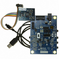
EVAL-ADAU1761Z
Description
Eval Board For ADAU1761
Manufacturer
Analog Devices Inc
Series
SigmaDSP®r
Specifications of EVAL-ADAU1761Z
Main Purpose
Audio, CODEC
Embedded
Yes, DSP
Utilized Ic / Part
ADAU1761
Primary Attributes
Stereo, 24-Bit, 8 ~ 96 kHz Sampling Rate, GUI Tool
Secondary Attributes
I²C and GPIO Interfaces, 2 Differential and 1 Stereo Single-Ended Analog Inputs and Outputs
Silicon Manufacturer
Analog Devices
Core Architecture
SigmaDSP
Silicon Core Number
ADAU1761
Silicon Family Name
SigmaDSP
Application Sub Type
Audio
Lead Free Status / RoHS Status
Lead free / RoHS Compliant
Available stocks
Company
Part Number
Manufacturer
Quantity
Price
Company:

Part Number:
EVAL-ADAU1761Z
Manufacturer:
Analog Devices Inc
Quantity:
135


ADAU1761
Analog Microphone Inputs
For microphone inputs, configure the part in either stereo
pseudo-differential mode or stereo full differential mode.
The LINN and LINP pins are the inverting and noninverting
inputs for the left channel, respectively. The RINN and RINP
pins are the inverting and noninverting inputs for the right
channel, respectively.
For a differential microphone input, connect the positive signal
to the noninverting input of the PGA and the negative signal to
the inverting input of the PGA, as shown in Figure 33. The PGA
settings are controlled with Register R8 (left differential input
volume control register, Address 0x400E) and Register R9 (right
differential input volume control register, Address 0x400F). The
PGA must first be enabled by setting the RDEN and LDEN bits.
The PGA can also be used for single-ended microphone inputs.
Connect LINP and/or RINP to the CM pin. In this configura-
tion, the signal connects to the inverting input of the PGA,
LINN and/or RINN, as shown in Figure 34.
MICROPHONE
MICROPHONE
MICROPHONE
MICROPHONE
Figure 34. Stereo Single-Ended Microphone Configuration
Figure 33. Stereo Differential Microphone Configuration
RIGHT
RIGHT
LEFT
LEFT
2kΩ
2kΩ
2kΩ
2kΩ
MICBIAS
MICBIAS
RINN
RINP
LINN
LINP
RINP
RINN
LINN
LINP
CM
RIGHT
RIGHT
LEFT
PGA
PGA
LEFT
–12dB TO
–12dB TO
PGA
PGA
+35.25dB
+35.25dB
–12dB TO
–12dB TO
+35.25dB
+35.25dB
ADAU1761
ADAU1761
RDBOOST[1:0]
LDBOOST[1:0]
LDBOOST[1:0]
RDBOOST[1:0]
0dB/20dB
0dB/20dB
0dB/20dB
0dB/20dB
MUTE/
MUTE/
MUTE/
MUTE/
Rev. C | Page 30 of 92
Analog Line Inputs
Line input signals can be accepted by any analog input. It is
possible to route signals on the RINN, RINP, LINN, and LINP
pins around the differential amplifier to their own amplifier and
to use these pins as single-ended line inputs by disabling the
LDEN and RDEN bits (Bit 0 in Register R8, Address 0x400E,
and Bit 0 in Register R9, Address 0x400F). Figure 35 depicts a
stereo single-ended line input using the RINN and LINN pins.
The LAUX and RAUX pins are single-ended line inputs. They
can be used together as a stereo single-ended auxiliary input, as
shown in Figure 35. These inputs can bypass the input gain
control, mixers, and ADCs to directly connect to the output
playback mixers (see auxiliary bypass in Figure 32).
Figure 35. Stereo Single-Ended Line Input with Stereo Auxiliary Bypass
RIGHT LINE
RIGHT AUX
LEFT LINE
LEFT AUX
INPUT
INPUT
INPUT
INPUT
RAUX
LAUX
RINN
LINN
AUXILIARY
BYPASS
–12dB TO +6dB
–12dB TO +6dB
ADAU1761
RINNG[2:0]
LINNG[2:0]
Related parts for EVAL-ADAU1761Z
Image
Part Number
Description
Manufacturer
Datasheet
Request
R


Part Number:
Description:
BOARD EVAL FOR SI270X-A
Manufacturer:
Silicon Laboratories Inc
Datasheet:

Part Number:
Description:
BUCK CONV REF DESIGN KIT IP1201
Manufacturer:
International Rectifier
Datasheet:
Part Number:
Description:
BOARD DEMO SYNC DUAL BUCK CNVTER
Manufacturer:
International Rectifier
Datasheet:
Part Number:
Description:
BOARD DEMO SYNC BUCK CONVETER
Manufacturer:
International Rectifier
Datasheet:

Part Number:
Description:
EVALBOARD/EB Omnidirectional microphone - Analog
Manufacturer:
Analog Devices
Datasheet:
Part Number:
Description:
EVALBOARD/EB Omnidirectional microphone - Analog
Manufacturer:
Analog Devices
Datasheet:


Part Number:
Description:
BOARD EVAL LED DRIVER LT3756
Manufacturer:
Linear Technology
Datasheet:

Part Number:
Description:
BOARD EVAL FOR AD7741/7742
Manufacturer:
Analog Devices Inc
Datasheet:

Part Number:
Description:
±1.7g Dual-Axis IMEMS Accelerometer Evaluation Board
Manufacturer:
Analog Devices Inc
Datasheet:

Part Number:
Description:
IC MULTIPLIER ANALOG 8-SOIC T/R
Manufacturer:
Analog Devices Inc
Datasheet:

Part Number:
Description:
IC ANALOG MULTIPLIER 8-DIP
Manufacturer:
Analog Devices Inc
Datasheet:
Part Number:
Description:
IC ANALOG MULTIPLIER 8-SOIC
Manufacturer:
Analog Devices Inc
Datasheet:
Part Number:
Description:
IC ANALOG MULTIPLIER 8-DIP
Manufacturer:
Analog Devices Inc
Datasheet: