EVAL-ADAU1761Z Analog Devices Inc, EVAL-ADAU1761Z Datasheet - Page 46
EVAL-ADAU1761Z
Manufacturer Part Number
EVAL-ADAU1761Z
Description
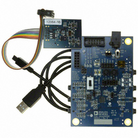
Eval Board For ADAU1761
Manufacturer
Analog Devices Inc
Series
SigmaDSP®r
Specifications of EVAL-ADAU1761Z
Main Purpose
Audio, CODEC
Embedded
Yes, DSP
Utilized Ic / Part
ADAU1761
Primary Attributes
Stereo, 24-Bit, 8 ~ 96 kHz Sampling Rate, GUI Tool
Secondary Attributes
I²C and GPIO Interfaces, 2 Differential and 1 Stereo Single-Ended Analog Inputs and Outputs
Silicon Manufacturer
Analog Devices
Core Architecture
SigmaDSP
Silicon Core Number
ADAU1761
Silicon Family Name
SigmaDSP
Application Sub Type
Audio
Lead Free Status / RoHS Status
Lead free / RoHS Compliant
Available stocks
Company
Part Number
Manufacturer
Quantity
Price
Company:

Part Number:
EVAL-ADAU1761Z
Manufacturer:
Analog Devices Inc
Quantity:
135


ADAU1761
NUMERIC FORMATS
DSP systems commonly use a standard numeric format.
Fractional numeric systems are specified by an A.B format,
where A is the number of bits to the left of the decimal point
and B is the number of bits to the right of the decimal point.
The ADAU1761 uses numeric format 5.23 for both the
parameter and data values.
Numeric Format 5.23
Linear range: −16.0 to (+16.0 − 1 LSB)
Examples:
1000 0000 0000 0000 0000 0000 0000 = −16.0
1110 0000 0000 0000 0000 0000 0000 = −4.0
1111 1000 0000 0000 0000 0000 0000 = −1.0
1111 1110 0000 0000 0000 0000 0000 = −0.25
1111 1111 0011 0011 0011 0011 0011 = −0.1
1111 1111 1111 1111 1111 1111 1111 = (1 LSB below 0)
0000 0000 0000 0000 0000 0000 0000 = 0
0000 0000 1100 1100 1100 1100 1101 = 0.1
0000 0010 0000 0000 0000 0000 0000 = 0.25
0000 1000 0000 0000 0000 0000 0000 = 1.0
0010 0000 0000 0000 0000 0000 0000 = 4.0
0111 1111 1111 1111 1111 1111 1111 = (16.0 − 1 LSB)
Figure 69. SigmaStudio Screen Shot
Rev. C | Page 46 of 92
The serial port accepts up to 24 bits on the input and is sign-
extended to the full 28 bits of the DSP core. This allows internal
gains of up to 24 dB without internal clipping.
A digital clipper circuit is used between the output of the DSP
core and the DACs or serial port outputs (see Figure 68). This
circuit clips the top four bits of the signal to produce a 24-bit
output with a range of 1.0 (minus 1 LSB) to −1.0. Figure 68
shows the maximum signal levels at each point in the data flow
in both binary and decibel levels.
DATA IN
PROGRAMMING
On power-up, the ADAU1761 must be configured with a clock-
ing scheme and then loaded with register settings. After the codec
signal path is set up, the DSP core can be programmed. There
are 1024 instruction cycles per audio sample, resulting in an
internal clock rate of 49.152 MHz when f
The part can be programmed easily using SigmaStudio, a graphical
tool provided by Analog Devices (see Figure 69). No knowledge
of writing line-level DSP code is required. More information
about SigmaStudio can be found at www.analog.com.
1.23
(0dB)
Figure 68. Numeric Precision and Clipping Structure
SERIAL
PORT
4-BIT SIGN EXTENSION
(0dB)
1.23
5.23
(24dB)
(5.23 FORMAT)
PROCESSING
SIGNAL
S
= 48 kHz.
(24dB)
5.23
CLIPPER
DIGITAL
(0dB)
1.23
Related parts for EVAL-ADAU1761Z
Image
Part Number
Description
Manufacturer
Datasheet
Request
R


Part Number:
Description:
BOARD EVAL FOR SI270X-A
Manufacturer:
Silicon Laboratories Inc
Datasheet:

Part Number:
Description:
BUCK CONV REF DESIGN KIT IP1201
Manufacturer:
International Rectifier
Datasheet:
Part Number:
Description:
BOARD DEMO SYNC DUAL BUCK CNVTER
Manufacturer:
International Rectifier
Datasheet:
Part Number:
Description:
BOARD DEMO SYNC BUCK CONVETER
Manufacturer:
International Rectifier
Datasheet:

Part Number:
Description:
EVALBOARD/EB Omnidirectional microphone - Analog
Manufacturer:
Analog Devices
Datasheet:
Part Number:
Description:
EVALBOARD/EB Omnidirectional microphone - Analog
Manufacturer:
Analog Devices
Datasheet:


Part Number:
Description:
BOARD EVAL LED DRIVER LT3756
Manufacturer:
Linear Technology
Datasheet:

Part Number:
Description:
BOARD EVAL FOR AD7741/7742
Manufacturer:
Analog Devices Inc
Datasheet:

Part Number:
Description:
±1.7g Dual-Axis IMEMS Accelerometer Evaluation Board
Manufacturer:
Analog Devices Inc
Datasheet:

Part Number:
Description:
IC MULTIPLIER ANALOG 8-SOIC T/R
Manufacturer:
Analog Devices Inc
Datasheet:

Part Number:
Description:
IC ANALOG MULTIPLIER 8-DIP
Manufacturer:
Analog Devices Inc
Datasheet:
Part Number:
Description:
IC ANALOG MULTIPLIER 8-SOIC
Manufacturer:
Analog Devices Inc
Datasheet:
Part Number:
Description:
IC ANALOG MULTIPLIER 8-DIP
Manufacturer:
Analog Devices Inc
Datasheet: