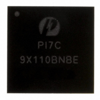
PI7C9X110BNBE Pericom Semiconductor, PI7C9X110BNBE Datasheet - Page 110

PI7C9X110BNBE
Manufacturer Part Number
PI7C9X110BNBE
Description
IC PCIE TO PCI REV BRG 160LFBGA
Manufacturer
Pericom Semiconductor
Specifications of PI7C9X110BNBE
Applications
PCI-to-PCI Bridge
Interface
I²C
Voltage - Supply
1.8 V
Package / Case
160-LBGA
Mounting Type
Surface Mount
Operating Temperature (min)
-40C
Operating Temperature Classification
Industrial
Operating Temperature (max)
85C
Rad Hardened
No
Maximum Operating Temperature
+ 85 C
Minimum Operating Temperature
- 40 C
Mounting Style
SMD/SMT
Lead Free Status / RoHS Status
Lead free / RoHS Compliant
Lead Free Status / RoHS Status
Lead free / RoHS Compliant, Compliant
Available stocks
Company
Part Number
Manufacturer
Quantity
Price
Company:
Part Number:
PI7C9X110BNBE
Manufacturer:
PLX
Quantity:
1 238
Company:
Part Number:
PI7C9X110BNBE
Manufacturer:
PERICOM31
Quantity:
193
Part Number:
PI7C9X110BNBE
Manufacturer:
PERICOM
Quantity:
20 000
7.5.85 SLOT STATUS REGISTER – OFFSET C8h
7.5.86 XPIP CONFIGURATION REGISTER 0 – OFFSET CCh
7.5.87 XPIP CONFIGURATION REGISTER 1 – OFFSET D0h
7.5.88 XPIP CONFIGURATION REGISTER 2 – OFFSET D4h
Pericom Semiconductor – Confidential
BIT
0
1
2
3
4
5
7:6
9:8
10
15:11
BIT
16
17
18
19
20
21
22
31:23
BIT
0
1
2
3
4
7:5
12:8
15:13
31:16
BIT
9:0
15:10
31:16
BIT
7:0
14:8
FUNCTION
Attention Button Present
Enable
Power Fault Detected Enable
MRL Sensor Changed
Enable
Presence Detect Changed
Enable
Command Completed
Interrupt Enable
Hot Plug Interrupt Enable
Attention Indicator Control
Power Indicator Control
Power Controller Control
Reserved
FUNCTION
Attention Button Pressed
Power Fault Detected
MRL Sensor Changed
Presence Detect Changed
Command Completed
MRL Sensor State
Presence Detect State
Reserved
FUNCTION
Hot Reset Enable
Loopback Function Enable
Cross Link Function Enable
Software Direct to
Configuration State when in
LTSSM state
Internal Selection for Debug
Mode
Negotiate Lane Number of
Times
TS1 Number Counter
Reserved
LTSSM Enter L1 Timer
Default Value
FUNCTION
L0’s Lifetime Timer
Reserved
L1 Lifetime Timer
FUNCTION
CDR Recovery Time (in the
number of FTS order sets)
L0’s Exit to L0 Latency
TYPE
TYPE
TYPE
TYPE
TYPE
RW
RW
RW
RW
RW
RW
RW
RW
RW
RW
RW
RW
RW
RW
RW
RW
RW
RW
RW
RW
RW
RO
RO
RO
RO
RO
RO
RO
RO
RO
RO
RO
Page 110 of 144
DESCRIPTION
Reset to 0
Reset to 0
Reset to 0
Reset to 0
Reset to 0
Reset to 0
Reset to 0
Reset to 0
Reset to 0
Reset to 0
DESCRIPTION
Reset to 0
Reset to 0
Reset to 0
Reset to 0
Reset to 0
Reset to 0
Reset to 0
Reset to 0
DESCRIPTION
Reset to 0
Reset to 0
Reset to 0
Reset to 0
Reset to 0
Reset to 3h
Reset to 10h
Reset to 0
Reset to 0400h
DESCRIPTION
Reset to 0
Reset to 0
Reset to 0
DESCRIPTION
Reset to 54h
A Fast Training Sequence order set composes of one K28.5 (COM) Symbol
and three K28.1 Symbols.
Reset to 2h
April 2010, Revision 3.0
PCIe-to-PCI Reversible Bridge
PI7C9X110


