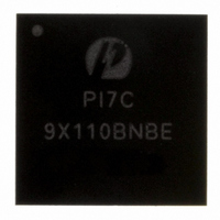
PI7C9X110BNBE Pericom Semiconductor, PI7C9X110BNBE Datasheet - Page 131

PI7C9X110BNBE
Manufacturer Part Number
PI7C9X110BNBE
Description
IC PCIE TO PCI REV BRG 160LFBGA
Manufacturer
Pericom Semiconductor
Specifications of PI7C9X110BNBE
Applications
PCI-to-PCI Bridge
Interface
I²C
Voltage - Supply
1.8 V
Package / Case
160-LBGA
Mounting Type
Surface Mount
Operating Temperature (min)
-40C
Operating Temperature Classification
Industrial
Operating Temperature (max)
85C
Rad Hardened
No
Maximum Operating Temperature
+ 85 C
Minimum Operating Temperature
- 40 C
Mounting Style
SMD/SMT
Lead Free Status / RoHS Status
Lead free / RoHS Compliant
Lead Free Status / RoHS Status
Lead free / RoHS Compliant, Compliant
Available stocks
Company
Part Number
Manufacturer
Quantity
Price
Company:
Part Number:
PI7C9X110BNBE
Manufacturer:
PLX
Quantity:
1 238
Company:
Part Number:
PI7C9X110BNBE
Manufacturer:
PERICOM31
Quantity:
193
Part Number:
PI7C9X110BNBE
Manufacturer:
PERICOM
Quantity:
20 000
8
In Forward bridge:
In Reverse bridge:
GPIO[0] : PCI slot Card Presence Detection Input
GPIO[1] : Attention Button Pressed Input
GPIO[2] : Power Indication Output
GPIO[3] : Attention Indication Output
GPIO[0] : PCIe slot Card Presence Detection Input
GPIO[1] : MRL Sensor Input
GPIO[2] : Reserved
GPIO[3] : Reserved
GPIO [3:1] of PI7C9X110 are defined for hot-plug usage if MSK_IN=1 during Reset. Please see configuration
register definition (offset 78h – 7Bh).
GPIO [3:0] are also defined the address bits of SMBUS device ID if SM Bus is selected (TM1=1). The address-
strapping table of SMBUS with GPIO [3:0] pins is defined in the following table:
Table 8-1 SM Bus Device ID Strapping
GPIO [3:0] pins can be further defined to serve other functions in the next generation Device.
Four GPI [3:0] and four GPO [3:0] have been added to PI7C9X110 when external arbiter is selected (CFN_L=1). If
external arbiter is selected, REQ_L [5:2] and GNT [5:2] will become the GPI [3:0] and GPO [3:0] respectively.
If Hot Plug Control is implemented thru PI7C9X110 device, the pin function of GPIO [3:0] configured in Forward
or Reverse Mode are defined as follow:
In Forward Mode:
In Reverse Mode:
Pericom Semiconductor – Confidential
GPIO PINS AND SM BUS ADDRESS
GPIO[0] : PCI slot Card Presence Detection Input
GPIO[1] : Attention Button Pressed Input
GPIO[2] : Power Indication Output
GPIO[3] : Attention Indication Output
SM Bus Address Bit
Address bit [7]
Address bit [6]
Address bit [5]
Address bit [4]
Address bit [3]
Address bit [2]
Address bit [1]
GPIO[0] : PCIe slot Card Presence Detection Input
GPIO[1] : MRL Sensor Input
GPIO[2] : Reserved
GPIO[3] : Reserved
Page 131 of 144
SM Bus device ID
= 1
= 1
= 0
= GPIO [3]
= GPIO [2]
= GPIO [1]
= GPIO [0]
April 2010, Revision 3.0
PCIe-to-PCI Reversible Bridge
PI7C9X110


