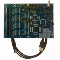
CDB5376 Cirrus Logic Inc, CDB5376 Datasheet - Page 40

CDB5376
Manufacturer Part Number
CDB5376
Description
EVALUATION BOARD FOR CS5376
Manufacturer
Cirrus Logic Inc
Datasheets
1.CS5371A-ISZR.pdf
(32 pages)
2.CS4373A-ISZ.pdf
(34 pages)
3.CS5376A-IQZR.pdf
(106 pages)
4.CDB5378.pdf
(16 pages)
5.CDB5376.pdf
(80 pages)
6.CDB5376.pdf
(16 pages)
Specifications of CDB5376
Main Purpose
Seismic Evaluation System
Embedded
Yes, MCU, 8-Bit
Utilized Ic / Part
CS3301A, CS3302A, CS4373A, CS5372A, CS5376A
Primary Attributes
Quad Digital Filter
Secondary Attributes
Graphical User Interface, SPI™ & USB Interfaces
Processor To Be Evaluated
CS330x, CS4373A, CS537x
Interface Type
USB
Lead Free Status / RoHS Status
Contains lead / RoHS non-compliant
Lead Free Status / RoHS Status
Lead free / RoHS Compliant, Contains lead / RoHS non-compliant
Other names
598-1778
- CS5371A-ISZR PDF datasheet
- CS4373A-ISZ PDF datasheet #2
- CS5376A-IQZR PDF datasheet #3
- CDB5378 PDF datasheet #4
- CDB5376 PDF datasheet #5
- CDB5376 PDF datasheet #6
- Current page: 40 of 106
- Download datasheet (2Mb)
10.4 Modulator Data Inputs
The MDATA input expects 1-bit ∆Σ data at a
512 kHz or 256 kHz rate. The input rate is selected
by a bit in the CONFIG register (0x00). By default,
MDATA is expected at 512 kHz.
The MDATA input one’s density is designed for
full scale positive at 86% and full scale negative at
14%, with absolute maximum over-range capabili-
ty to 93% and 7%. These raw ∆Σ inputs are deci-
mated and filtered by the digital filter to create 24-
bit samples at the output rate.
40
10.5 Modulator Flag Inputs
A high MFLAG input signal indicates the corre-
sponding ∆Σ modulator has become unstable due
to an analog over-range input signal. Once the
over-range signal is reduced, the modulator recov-
ers stability and the MFLAG signal is cleared.
The MFLAG inputs are mapped to status bits in the
SD port, and are associated with each sample when
written. See “Serial Data Port” on page 61 for more
information on the MFLAG error bits in the SD
port status byte.
CS5376A
DS612F4
Related parts for CDB5376
Image
Part Number
Description
Manufacturer
Datasheet
Request
R

Part Number:
Description:
Development Kit
Manufacturer:
Cirrus Logic Inc
Datasheet:

Part Number:
Description:
Development Kit
Manufacturer:
Cirrus Logic Inc
Datasheet:

Part Number:
Description:
High-efficiency PFC + Fluorescent Lamp Driver Reference Design
Manufacturer:
Cirrus Logic Inc
Datasheet:

Part Number:
Description:
Development Kit
Manufacturer:
Cirrus Logic Inc
Datasheet:

Part Number:
Description:
Development Kit
Manufacturer:
Cirrus Logic Inc
Datasheet:

Part Number:
Description:
Development Kit
Manufacturer:
Cirrus Logic Inc
Datasheet:

Part Number:
Description:
Development Kit
Manufacturer:
Cirrus Logic Inc
Datasheet:

Part Number:
Description:
Development Kit
Manufacturer:
Cirrus Logic Inc
Datasheet:

Part Number:
Description:
Development Kit
Manufacturer:
Cirrus Logic Inc
Datasheet:

Part Number:
Description:
EVALUATION BOARD FOR CS8427
Manufacturer:
Cirrus Logic Inc
Datasheet:

Part Number:
Description:
BOARD EVAL FOR CS8416 RCVR
Manufacturer:
Cirrus Logic Inc
Datasheet:

Part Number:
Description:
EVALUATION BOARD FOR CS8420
Manufacturer:
Cirrus Logic Inc
Datasheet:

Part Number:
Description:
KIT DEVELOPMENT EP9315 ARM9
Manufacturer:
Cirrus Logic Inc
Datasheet:

Part Number:
Description:
KIT DEVELOPMENT EP9302 ARM9
Manufacturer:
Cirrus Logic Inc
Datasheet:


