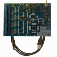
CDB5376 Cirrus Logic Inc, CDB5376 Datasheet - Page 75

CDB5376
Manufacturer Part Number
CDB5376
Description
EVALUATION BOARD FOR CS5376
Manufacturer
Cirrus Logic Inc
Datasheets
1.CS5371A-ISZR.pdf
(32 pages)
2.CS4373A-ISZ.pdf
(34 pages)
3.CS5376A-IQZR.pdf
(106 pages)
4.CDB5378.pdf
(16 pages)
5.CDB5376.pdf
(80 pages)
6.CDB5376.pdf
(16 pages)
Specifications of CDB5376
Main Purpose
Seismic Evaluation System
Embedded
Yes, MCU, 8-Bit
Utilized Ic / Part
CS3301A, CS3302A, CS4373A, CS5372A, CS5376A
Primary Attributes
Quad Digital Filter
Secondary Attributes
Graphical User Interface, SPI™ & USB Interfaces
Processor To Be Evaluated
CS330x, CS4373A, CS537x
Interface Type
USB
Lead Free Status / RoHS Status
Contains lead / RoHS non-compliant
Lead Free Status / RoHS Status
Lead free / RoHS Compliant, Contains lead / RoHS non-compliant
Other names
598-1778
- CS5371A-ISZR PDF datasheet
- CS4373A-ISZ PDF datasheet #2
- CS5376A-IQZR PDF datasheet #3
- CDB5378 PDF datasheet #4
- CDB5376 PDF datasheet #5
- CDB5376 PDF datasheet #6
- Current page: 75 of 106
- Download datasheet (2Mb)
CS5376A
TRST
TAP
TDO
TMS
Controller
TCK
TDI
Boundary Scan Cells
Figure 40. JTAG Block Diagram
21.BOUNDARY SCAN JTAG
The CS5376A includes an IEEE 1149.1 boundary scan JTAG port to test PCB interconnections. Refer to
the IEEE 1149.1 specification for more information about boundary scan testing.
21.1 Pin Descriptions
TRST - Pin 1
Reset input for the test access port (TAP) controller and all boundary scan cells, active low. Connect to
GND to disable the JTAG port.
TMS - Pin 2
Serial input to select the JTAG test mode.
TCK - Pin 3
Clock input to the TAP controller.
TDI - Pin 4
Serial input to the scan chain or TAP controller.
TDO - Pin 5
Serial output from the scan chain or TAP controller.
21.2 JTAG Architecture
The JTAG test circuitry consists of a test access port (TAP) controller and boundary scan cells connected
to each pin. The boundary scan cells are linked together to create a scan chain around the CS5376A.
DS612F4
75
Related parts for CDB5376
Image
Part Number
Description
Manufacturer
Datasheet
Request
R

Part Number:
Description:
Development Kit
Manufacturer:
Cirrus Logic Inc
Datasheet:

Part Number:
Description:
Development Kit
Manufacturer:
Cirrus Logic Inc
Datasheet:

Part Number:
Description:
High-efficiency PFC + Fluorescent Lamp Driver Reference Design
Manufacturer:
Cirrus Logic Inc
Datasheet:

Part Number:
Description:
Development Kit
Manufacturer:
Cirrus Logic Inc
Datasheet:

Part Number:
Description:
Development Kit
Manufacturer:
Cirrus Logic Inc
Datasheet:

Part Number:
Description:
Development Kit
Manufacturer:
Cirrus Logic Inc
Datasheet:

Part Number:
Description:
Development Kit
Manufacturer:
Cirrus Logic Inc
Datasheet:

Part Number:
Description:
Development Kit
Manufacturer:
Cirrus Logic Inc
Datasheet:

Part Number:
Description:
Development Kit
Manufacturer:
Cirrus Logic Inc
Datasheet:

Part Number:
Description:
EVALUATION BOARD FOR CS8427
Manufacturer:
Cirrus Logic Inc
Datasheet:

Part Number:
Description:
BOARD EVAL FOR CS8416 RCVR
Manufacturer:
Cirrus Logic Inc
Datasheet:

Part Number:
Description:
EVALUATION BOARD FOR CS8420
Manufacturer:
Cirrus Logic Inc
Datasheet:

Part Number:
Description:
KIT DEVELOPMENT EP9315 ARM9
Manufacturer:
Cirrus Logic Inc
Datasheet:

Part Number:
Description:
KIT DEVELOPMENT EP9302 ARM9
Manufacturer:
Cirrus Logic Inc
Datasheet:


