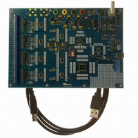
CDB5376 Cirrus Logic Inc, CDB5376 Datasheet - Page 47

CDB5376
Manufacturer Part Number
CDB5376
Description
EVALUATION BOARD FOR CS5376
Manufacturer
Cirrus Logic Inc
Datasheets
1.CS5371A-ISZR.pdf
(32 pages)
2.CS4373A-ISZ.pdf
(34 pages)
3.CS5376A-IQZR.pdf
(106 pages)
4.CDB5378.pdf
(16 pages)
5.CDB5376.pdf
(80 pages)
6.CDB5376.pdf
(16 pages)
Specifications of CDB5376
Main Purpose
Seismic Evaluation System
Embedded
Yes, MCU, 8-Bit
Utilized Ic / Part
CS3301A, CS3302A, CS4373A, CS5372A, CS5376A
Primary Attributes
Quad Digital Filter
Secondary Attributes
Graphical User Interface, SPI™ & USB Interfaces
Processor To Be Evaluated
CS330x, CS4373A, CS537x
Interface Type
USB
Lead Free Status / RoHS Status
Contains lead / RoHS non-compliant
Lead Free Status / RoHS Status
Lead free / RoHS Compliant, Contains lead / RoHS non-compliant
Other names
598-1778
13.FIR FILTER
The finite impulse response (FIR) filter block con-
sists of two cascaded stages, FIR1 and FIR2. It
compensates for SINC filter droop and creates a
low-pass corner to block aliased components of the
input signal.
On-chip linear phase or minimum phase coeffi-
cients can be selected using a configuration com-
mand, or the coefficients can be programmed for a
custom filter response.
13.1 FIR1 Filter
The FIR1 filter stage has a decimate by four archi-
tecture. It compensates for SINC filter droop and
flattens the magnitude response of the pass band.
The on-chip linear and minimum phase coefficient
sets are 48-tap, with a maximum 255 programma-
ble coefficients. All coefficients are normalized to
24-bit two’s complement full scale, 0x7FFFFF.
The characteristic equation for FIR1 is a convolu-
tion of the input values, X(n), and the filter coeffi-
cients, h(k), to produce an output value, Y.
Y = [h(k)*X(n-k)] + [h(k+1)*X(n-(k+1))] + ...
DS612F4
FIR1 Filter - decimate by 4
Figure 25. FIR Filter Block Diagram
13.2 FIR2 Filter
The FIR2 filter stage has a decimate by two archi-
tecture. It creates a low-pass brick wall filter to
block aliased components of the input signal.
The on-chip linear and minimum phase coefficient
sets are 126-tap, with a maximum 255 programma-
ble coefficients. All coefficients are normalized to
24-bit two’s complement full scale, 0x7FFFFF.
The characteristic equation for FIR2 is a convolu-
tion of the input values, X(n), and the filter coeffi-
cients, h(k), to produce an output value, Y.
Y = [h(k)*X(n-k)] + [h(k+1)*X(n-(k+1))] + ...
13.3 On-Chip FIR Coefficients
Two sets of on-chip linear phase and minimum
phase coefficients are available for FIR1 and FIR2.
Performance of the on-chip coefficient sets is very
good, with excellent ripple and stop band charac-
teristics as described in Figure 26 and Table 12.
Which on-chip coefficient set to use is selected by
a data word following the ‘Write ROM Coeffi-
cients’ configuration command. See “Filter Coeffi-
cient Selection” on page 41 for information about
selecting on-chip coefficient sets.
FIR2 Filter - decimate by 2
CS5376A
47


