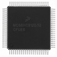
MCHC912B32CFUE8 Freescale Semiconductor, MCHC912B32CFUE8 Datasheet - Page 70

MCHC912B32CFUE8
Manufacturer Part Number
MCHC912B32CFUE8
Description
IC MCU 32K FLASH 8MHZ 80-QFP
Manufacturer
Freescale Semiconductor
Series
HC12r
Datasheet
1.MCHC912B32CFUE8.pdf
(334 pages)
Specifications of MCHC912B32CFUE8
Core Processor
CPU12
Core Size
16-Bit
Speed
8MHz
Connectivity
SCI, SPI
Peripherals
POR, PWM, WDT
Number Of I /o
63
Program Memory Size
32KB (32K x 8)
Program Memory Type
FLASH
Eeprom Size
768 x 8
Ram Size
1K x 8
Voltage - Supply (vcc/vdd)
4.5 V ~ 5.5 V
Data Converters
A/D 8x10b
Oscillator Type
External
Operating Temperature
-40°C ~ 85°C
Package / Case
80-QFP
Cpu Family
HC12
Device Core Size
16b
Frequency (max)
8MHz
Interface Type
SCI/SPI
Total Internal Ram Size
1KB
# I/os (max)
63
Operating Supply Voltage (typ)
5V
Operating Supply Voltage (max)
5.5V
Operating Supply Voltage (min)
4.5V
On-chip Adc
8-chx10-bit
Instruction Set Architecture
CISC
Operating Temp Range
-40C to 85C
Operating Temperature Classification
Industrial
Mounting
Surface Mount
Pin Count
80
Package Type
PQFP
Package
80PQFP
Family Name
HC12
Maximum Speed
8 MHz
Operating Supply Voltage
5 V
Data Bus Width
16 Bit
Number Of Programmable I/os
63
Processor Series
HC912B
Core
HC12
Data Ram Size
1 KB
Maximum Clock Frequency
8 MHz
Maximum Operating Temperature
+ 85 C
Mounting Style
SMD/SMT
3rd Party Development Tools
EWHCS12
Development Tools By Supplier
M68EVB912B32E
Minimum Operating Temperature
- 40 C
Lead Free Status / RoHS Status
Lead free / RoHS Compliant
Available stocks
Company
Part Number
Manufacturer
Quantity
Price
Company:
Part Number:
MCHC912B32CFUE8
Manufacturer:
Freescale Semiconductor
Quantity:
10 000
- Current page: 70 of 334
- Download datasheet (2Mb)
Resets and Interrupts
4.4 Latching of Interrupts
XIRQ is always level triggered and IRQ can be selected as a level-triggered interrupt. These
level-triggered interrupt pins should be released only during the appropriate interrupt service routine.
Generally, the interrupt service routine will handshake with the interrupting logic to release the pin. In this
way, the MCU will never start the interrupt service sequence only to determine that there is no longer an
interrupt source. In the event that this does occur, the trap vector will be taken.
If IRQ is selected as an edge-triggered interrupt, the hold time of the level after the active edge is
independent of when the interrupt is serviced. As long as the minimum hold time is met, the interrupt will
be latched inside the MCU. In this case, the IRQ edge interrupt latch is cleared automatically when the
interrupt is serviced.
All of the remaining interrupts are latched by the MCU with a flag bit. These interrupt flags should be
cleared during an interrupt service routine or when the interrupts are masked by the I bit. By doing this,
the MCU will never get an unknown interrupt source and take the trap vector.
4.5 Interrupt Control and Priority Registers
This section describes the interrupt control and priority registers.
4.5.1 Interrupt Control Register
Read: Anytime
Write: Varies from bit to bit
IRQE — IRQ Edge-Sensitive Only Bit
IRQEN — External IRQ Enable Bit
DLY — Oscillator Startup Delay on Exit from Stop Mode Bit
70
IRQE can be written once in normal modes. In special modes, IRQE can be written anytime, but the
first write is ignored.
IRQEN can be written anytime in all modes. The IRQ pin has an internal pullup.
DLY can be written once in normal modes. In special modes, DLY can be written anytime.
The delay time of about 4096 cycles is based on the E-clock rate.
1 = IRQ pin responds only to falling edges.
0 = IRQ pin responds to low levels.
1 = IRQ pin connected to interrupt logic
0 = IRQ pin disconnected from interrupt logic
1 = Stabilization delay on exit from stop mode
0 = No stabilization delay on exit from stop mode
Address: $001E
Reset:
Read:
Write:
IRQE
Bit 7
0
Figure 4-1. Interrupt Control Register (INTCR)
IRQEN
6
1
M68HC12B Family Data Sheet, Rev. 9.1
DLY
5
1
4
0
0
3
0
0
2
0
0
1
0
0
Freescale Semiconductor
Bit 0
0
0
Related parts for MCHC912B32CFUE8
Image
Part Number
Description
Manufacturer
Datasheet
Request
R
Part Number:
Description:
Manufacturer:
Freescale Semiconductor, Inc
Datasheet:
Part Number:
Description:
Manufacturer:
Freescale Semiconductor, Inc
Datasheet:
Part Number:
Description:
Manufacturer:
Freescale Semiconductor, Inc
Datasheet:
Part Number:
Description:
Manufacturer:
Freescale Semiconductor, Inc
Datasheet:
Part Number:
Description:
Manufacturer:
Freescale Semiconductor, Inc
Datasheet:
Part Number:
Description:
Manufacturer:
Freescale Semiconductor, Inc
Datasheet:
Part Number:
Description:
Manufacturer:
Freescale Semiconductor, Inc
Datasheet:
Part Number:
Description:
Manufacturer:
Freescale Semiconductor, Inc
Datasheet:
Part Number:
Description:
Manufacturer:
Freescale Semiconductor, Inc
Datasheet:
Part Number:
Description:
Manufacturer:
Freescale Semiconductor, Inc
Datasheet:
Part Number:
Description:
Manufacturer:
Freescale Semiconductor, Inc
Datasheet:
Part Number:
Description:
Manufacturer:
Freescale Semiconductor, Inc
Datasheet:
Part Number:
Description:
Manufacturer:
Freescale Semiconductor, Inc
Datasheet:
Part Number:
Description:
Manufacturer:
Freescale Semiconductor, Inc
Datasheet:
Part Number:
Description:
Manufacturer:
Freescale Semiconductor, Inc
Datasheet:


