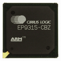
EP9315-CBZ Cirrus Logic Inc, EP9315-CBZ Datasheet - Page 240

EP9315-CBZ
Manufacturer Part Number
EP9315-CBZ
Description
IC ARM9 SOC ENH UNIV 352PBGA
Manufacturer
Cirrus Logic Inc
Series
EP9r
Specifications of EP9315-CBZ
Core Size
16/32-Bit
Core Processor
ARM9
Speed
200MHz
Connectivity
EBI/EMI, EIDE, Ethernet, I²C, IrDA, Keypad/Touchscreen, PCMCIA, SPI, UART/USART, USB
Peripherals
AC'97, DMA, I²:S, LCD, LED, MaverickKey, POR, PWM, WDT
Number Of I /o
16
Program Memory Type
ROMless
Ram Size
32K x 8
Voltage - Supply (vcc/vdd)
1.65 V ~ 3.6 V
Data Converters
A/D 8x12b
Oscillator Type
External
Operating Temperature
0°C ~ 70°C
Package / Case
352-BGA
Controller Family/series
(ARM9)
No. Of I/o's
16
Cpu Speed
200MHz
No. Of Timers
5
Digital Ic Case Style
BGA
Supply Voltage Range
1.65V To 1.94V, 3V To 3.6V
Embedded Interface Type
SPI
Rohs Compliant
Yes
Processor Series
EP93xx
Core
ARM920T
Data Bus Width
32 bit
3rd Party Development Tools
MDK-ARM, RL-ARM, ULINK2
Development Tools By Supplier
EDB9315A-Z
Case
BGA
Dc
06+
Lead Free Status / RoHS Status
Lead free / RoHS Compliant
For Use With
598-1144 - KIT DEVELOPMENT EP9315 ARM9
Eeprom Size
-
Program Memory Size
-
Lead Free Status / Rohs Status
Details
Other names
598-1139
Available stocks
Company
Part Number
Manufacturer
Quantity
Price
Part Number:
EP9315-CBZ
Manufacturer:
CIRRUS
Quantity:
20 000
- Current page: 240 of 824
- Download datasheet (13Mb)
7
7-58
Raster Engine With Analog/LCD Integrated Timing and Interface
EP93xx User’s Guide
C:
M:
M3
C3
0
0
0
X
1
0
0
0
0
0
C2
M2
X
0
1
1
1
0
0
0
0
1
Table 7-13. Color Mode Definition Table
Table 7-14. Blink Mode Definition Table
M1
C1
0
0
0
1
X
0
0
1
1
0
Copyright 2007 Cirrus Logic
Writing a Dual Scan value to this bit selects whether the
display is used in single scan mode, or dual scan mode
where the display is divided into a ‘top’ half and a ‘bottom’
half. In dual scan mode, the video frame buffer in SDRAM
must be organized such that ‘top’ and ‘bottom’ pixels
alternate in consecutive locations. ‘Top’ and ‘bottom’ pixels
are fetched and input to the Raster Engine’s video
pipeline. The output shifter is set up to drive the top and
bottom half screen data at the same time. Dual scan mode
is intended for passive matrix LCD screens that require
both halves of the screen to be scanned out at the same
time. However, dual scan mode could also be used to
drive two separate synchronized displays, each with
different data.
0 - Single Scan (full page)
1 - Dual Scan (two half pages)
Color - Read/Write
The Color Mode is specified by selecting a value from
Table 7-13
Mode - Read/Write
The Blink Mode is specified by selecting a value from
Table 7-14
C0
M0
X
0
0
1
0
0
1
0
1
0
and writing it to this field.
and writing it to this field.
Blink to background register Value
Pixels ANDed with Blink Mask
Pixels ORed with Blink Mask
Grayscale Palettes Enabled
Triple 8 bits per channel
XORed with Blink Mask
16-bit 565 color mode
16-bit 555 color mode
Blink Mode Disabled
Use LUT Data
Color Mode
Blink Mode
DS785UM1
Related parts for EP9315-CBZ
Image
Part Number
Description
Manufacturer
Datasheet
Request
R

Part Number:
Description:
IC ARM920T MCU 200MHZ 352-PBGA
Manufacturer:
Cirrus Logic Inc
Datasheet:

Part Number:
Description:
32-Bit Microcontroller IC
Manufacturer:
Cirrus Logic Inc
Datasheet:

Part Number:
Description:
IC ARM920T MCU 200MHZ 352-PBGA
Manufacturer:
Cirrus Logic Inc
Datasheet:

Part Number:
Description:
MCU, MPU & DSP Development Tools Eval Bd Uni. ARM9 SOC Processor
Manufacturer:
Cirrus Logic Inc
Datasheet:

Part Number:
Description:
Development Kit
Manufacturer:
Cirrus Logic Inc
Datasheet:

Part Number:
Description:
Development Kit
Manufacturer:
Cirrus Logic Inc
Datasheet:

Part Number:
Description:
High-efficiency PFC + Fluorescent Lamp Driver Reference Design
Manufacturer:
Cirrus Logic Inc
Datasheet:

Part Number:
Description:
Development Kit
Manufacturer:
Cirrus Logic Inc
Datasheet:

Part Number:
Description:
Development Kit
Manufacturer:
Cirrus Logic Inc
Datasheet:

Part Number:
Description:
Development Kit
Manufacturer:
Cirrus Logic Inc
Datasheet:

Part Number:
Description:
Development Kit
Manufacturer:
Cirrus Logic Inc
Datasheet:

Part Number:
Description:
Development Kit
Manufacturer:
Cirrus Logic Inc
Datasheet:

Part Number:
Description:
Development Kit
Manufacturer:
Cirrus Logic Inc
Datasheet:

Part Number:
Description:
Ref Bd For Speakerbar MSA & DSP Products
Manufacturer:
Cirrus Logic Inc


