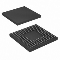
AT91M55800A-33CJ Atmel, AT91M55800A-33CJ Datasheet - Page 59

AT91M55800A-33CJ
Manufacturer Part Number
AT91M55800A-33CJ
Description
IC ARM MCU 16BIT 176BGA
Manufacturer
Atmel
Series
AT91SAMr
Specifications of AT91M55800A-33CJ
Core Processor
ARM7
Core Size
16/32-Bit
Speed
33MHz
Connectivity
EBI/EMI, SPI, UART/USART
Peripherals
POR, WDT
Number Of I /o
58
Program Memory Type
ROMless
Ram Size
8K x 8
Voltage - Supply (vcc/vdd)
2.7 V ~ 3.6 V
Data Converters
A/D 8x10b; D/A 2x10b
Oscillator Type
Internal
Operating Temperature
-40°C ~ 85°C
Package / Case
176-LFBGA
Processor Series
AT91Mx
Core
ARM7TDMI
Data Bus Width
32 bit
Data Ram Size
8 KB
Interface Type
EBI, SPI, USART
Maximum Clock Frequency
33 MHz
Number Of Programmable I/os
58
Number Of Timers
10 bit
Operating Supply Voltage
3 V to 3.6 V
Maximum Operating Temperature
+ 85 C
Mounting Style
SMD/SMT
3rd Party Development Tools
JTRACE-ARM-2M, MDK-ARM, RL-ARM, ULINK2
Development Tools By Supplier
AT91EB55
Minimum Operating Temperature
- 40 C
On-chip Adc
10 bit, 8 Channel
On-chip Dac
8 bit, 2 Channel
Cpu Family
AT91
Device Core
ARM7TDMI
Device Core Size
32b
Frequency (max)
33MHz
Program Memory Size
Not Required
Total Internal Ram Size
8KB
# I/os (max)
58
Number Of Timers - General Purpose
6
Operating Supply Voltage (typ)
3.3V
Operating Supply Voltage (max)
3.6V
Operating Supply Voltage (min)
2.7V
Instruction Set Architecture
RISC
Operating Temp Range
-40C to 85C
Operating Temperature Classification
Industrial
Mounting
Surface Mount
Pin Count
176
Package Type
BGA
For Use With
AT91EB55 - KIT EVAL FOR ARM AT91M55800A
Lead Free Status / RoHS Status
Contains lead / RoHS non-compliant
Eeprom Size
-
Program Memory Size
-
Lead Free Status / Rohs Status
Lead free / RoHS Compliant
Available stocks
Company
Part Number
Manufacturer
Quantity
Price
Company:
Part Number:
AT91M55800A-33CJ
Manufacturer:
ATMEL
Quantity:
590
Part Number:
AT91M55800A-33CJ
Manufacturer:
ATMEL/爱特梅尔
Quantity:
20 000
Company:
Part Number:
AT91M55800A-33CJ SL383
Manufacturer:
Atmel
Quantity:
10 000
12.4
12.5
12.6
1745F–ATARM–06-Sep-07
System Clock
Peripheral Clocks
Shut-down and Wake-up
The AT91M55800A has only one system clock: the ARM Core clock. It can be enabled and dis-
abled by writing to the System Clock Enable (APMC_SCER) and System Clock Disable
Registers (APMC_SCDR). The status of the ARM Core clock (at least for debug purposes) can
be read in the System Clock Status Register (APMC_SCSR).
The ARM Core clock is enabled after a reset and is automatically re-enabled by any enabled
interrupt.
When the ARM Core clock is disabled, the current instruction is finished before the clock is
stopped.
Note:
Each peripheral clock integrated in the AT91M55800A can be individually enabled and disabled
by writing to the Peripheral Clock Enable (APMC_PCER) and Peripheral Clock Disable
(APMC_PCDR) Registers. The status of the peripheral clocks can be read in the Peripheral
Clock Status Register (APMC_PCSR).
When a peripheral clock is disabled, the clock is immediately stopped. When the clock is re-
enabled, the peripheral resumes action where it left off.
In order to stop a peripheral, it is recommended that the system software waits until the periph-
eral has executed its last programmed operation before disabling the clock. This is to avoid data
corruption or erroneous behavior of the system.
The peripheral clocks are automatically disabled after a reset.
The bits that control the peripheral clocks are the same as those that control the Interrupt
Sources in the AIC.
The APMC (Advanced Power Management Controller) integrates shut-down and wake-up logic
to control an external main power supply. This logic is supplied by the Battery Backup Power.
This feature makes the Power-down mode possible.
If the SHDN pin is connected to the shut-down pin of the main power supply, the Shut-down
command (SHDALC) in APMC_PCR disables the main power. The shut-down input of the con-
verter is generally pulled up or down by a resistor, depending on its active level.
There are 3 ways to exit Power-down mode and restart the main power:
Figure 12-7 shows a typical application using the Shut-down and Wake-up features.
• An alarm programmed in the RTC occurs and the bit ALWKEN in APMC_PMR is set.
• An edge defined by the field WKEDG in APMC_PMR occurs on the pin WAKEUP.
• The user opens the Shut-down line with an external jumper or push-button.
Stopping the ARM Core does not prevent PDC transfers.
AT91M5880A
59


