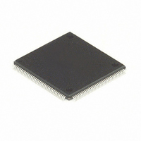
MC68HC16Z1CAG25 Freescale Semiconductor, MC68HC16Z1CAG25 Datasheet - Page 100

MC68HC16Z1CAG25
Manufacturer Part Number
MC68HC16Z1CAG25
Description
IC MCU 16BIT 25MHZ 144-LQFP
Manufacturer
Freescale Semiconductor
Series
HC16r
Datasheet
1.MC68HC16Z1VEH16.pdf
(500 pages)
Specifications of MC68HC16Z1CAG25
Core Processor
CPU16
Core Size
16-Bit
Speed
25MHz
Connectivity
EBI/EMI, SCI, SPI
Peripherals
POR, PWM, WDT
Number Of I /o
16
Program Memory Type
ROMless
Ram Size
1K x 8
Voltage - Supply (vcc/vdd)
2.7 V ~ 5.5 V
Data Converters
A/D 8x10b
Oscillator Type
Internal
Operating Temperature
-40°C ~ 85°C
Package / Case
144-LQFP
Cpu Family
HC16
Device Core Size
16b
Frequency (max)
25MHz
Interface Type
SCI/SPI/UART
Program Memory Size
Not Required
Total Internal Ram Size
1KB
# I/os (max)
16
Number Of Timers - General Purpose
11
Operating Supply Voltage (typ)
3.3/5V
Operating Supply Voltage (max)
5.5V
Operating Supply Voltage (min)
2.7V
On-chip Adc
8-chx10-bit
Instruction Set Architecture
CISC
Operating Temp Range
-40C to 85C
Operating Temperature Classification
Industrial
Mounting
Surface Mount
Pin Count
144
Package Type
LQFP
Controller Family/series
68HC16
No. Of I/o's
16
Ram Memory Size
1KB
Cpu Speed
25MHz
No. Of Timers
2
Embedded Interface Type
QSPI, SCI
Rohs Compliant
Yes
Processor Series
HC16Z
Core
CPU16
Data Bus Width
16 bit
Data Ram Size
1 KB
Maximum Clock Frequency
25 MHz
Number Of Programmable I/os
16
Number Of Timers
11
Maximum Operating Temperature
+ 85 C
Mounting Style
SMD/SMT
Minimum Operating Temperature
- 40 C
Lead Free Status / RoHS Status
Lead free / RoHS Compliant
Eeprom Size
-
Program Memory Size
-
Lead Free Status / Rohs Status
Compliant
Available stocks
Company
Part Number
Manufacturer
Quantity
Price
Company:
Part Number:
MC68HC16Z1CAG25
Manufacturer:
FREESCAL
Quantity:
455
Company:
Part Number:
MC68HC16Z1CAG25
Manufacturer:
Freescale Semiconductor
Quantity:
10 000
- Current page: 100 of 500
- Download datasheet (6Mb)
4.13.5 Multiple Exceptions
4.13.6 RTI Instruction
4.14 Development Support
4.14.1 Deterministic Opcode Tracking
4-40
Each exception has a hardware priority based upon its relative importance to system
operation. Asynchronous exceptions have higher priorities than synchronous excep-
tions. Exception processing for multiple exceptions is completed by priority, from high-
est to lowest. Priority governs the order in which exception processing occurs, not the
order in which exception handlers are executed.
Unless a bus error, a breakpoint, or a reset occurs during exception processing, the
first instruction of all exception handler routines is guaranteed to execute before an-
other exception is processed. Because interrupt exceptions have higher priority than
synchronous exceptions, the first instruction in an interrupt handler is executed before
other interrupts are sensed.
Bus error, breakpoint, and reset exceptions that occur during exception processing of
a previous exception are processed before the first instruction of that exception’s han-
dler routine. The converse is not true. If an interrupt occurs during bus error exception
processing, for example, the first instruction of the exception handler is executed be-
fore interrupts are sensed. This permits the exception handler to mask interrupts dur-
ing execution.
Refer to
cerning interrupts and system reset. For information concerning processing of specific
exceptions, refer to the CPU16 Reference Manual (CPU16RM/AD).
The return-from-interrupt instruction (RTI) must be the last instruction in all exception
handlers except the RESET handler. RTI pulls the exception stack frame that was
pushed onto the system stack during exception processing, and restores processor
state. Normal program flow resumes at the address of the instruction that follows the
last instruction executed before exception processing began.
RTI is not used in the RESET handler because RESET initializes the stack pointer and
does not create a stack frame.
The CPU16 incorporates powerful tools for tracking program execution and for system
debugging. These tools are deterministic opcode tracking, breakpoint exceptions, and
background debug mode. Judicious use of CPU16 capabilities permits in-circuit emu-
lation and system debugging using a bus state analyzer, a simple serial interface, and
a terminal.
The CPU16 has two multiplexed outputs, IPIPE0 and IPIPE1, that enable external
hardware to monitor the instruction pipeline during normal program execution. The sig-
nals IPIPE0 and IPIPE1 can be demultiplexed into six pipeline state signals that allow
a state analyzer to synchronize with instruction stream activity.
SECTION 5 SYSTEM INTEGRATION MODULE
Freescale Semiconductor, Inc.
For More Information On This Product,
CENTRAL PROCESSING UNIT
Go to: www.freescale.com
for detailed information con-
M68HC16 Z SERIES
USER’S MANUAL
Related parts for MC68HC16Z1CAG25
Image
Part Number
Description
Manufacturer
Datasheet
Request
R
Part Number:
Description:
Manufacturer:
Freescale Semiconductor, Inc
Datasheet:
Part Number:
Description:
Manufacturer:
Freescale Semiconductor, Inc
Datasheet:
Part Number:
Description:
Manufacturer:
Freescale Semiconductor, Inc
Datasheet:
Part Number:
Description:
Manufacturer:
Freescale Semiconductor, Inc
Datasheet:
Part Number:
Description:
Manufacturer:
Freescale Semiconductor, Inc
Datasheet:
Part Number:
Description:
Manufacturer:
Freescale Semiconductor, Inc
Datasheet:
Part Number:
Description:
Manufacturer:
Freescale Semiconductor, Inc
Datasheet:
Part Number:
Description:
Manufacturer:
Freescale Semiconductor, Inc
Datasheet:
Part Number:
Description:
Manufacturer:
Freescale Semiconductor, Inc
Datasheet:
Part Number:
Description:
Manufacturer:
Freescale Semiconductor, Inc
Datasheet:
Part Number:
Description:
Manufacturer:
Freescale Semiconductor, Inc
Datasheet:
Part Number:
Description:
Manufacturer:
Freescale Semiconductor, Inc
Datasheet:
Part Number:
Description:
Manufacturer:
Freescale Semiconductor, Inc
Datasheet:
Part Number:
Description:
Manufacturer:
Freescale Semiconductor, Inc
Datasheet:
Part Number:
Description:
Manufacturer:
Freescale Semiconductor, Inc
Datasheet:


