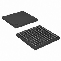
AT91SAM7SE256-CU Atmel, AT91SAM7SE256-CU Datasheet - Page 150

AT91SAM7SE256-CU
Manufacturer Part Number
AT91SAM7SE256-CU
Description
IC ARM7 MCU FLASH 256K 144-LFBGA
Manufacturer
Atmel
Series
AT91SAMr
Datasheet
1.AT91SAM7SE256-AU.pdf
(673 pages)
Specifications of AT91SAM7SE256-CU
Core Processor
ARM7
Core Size
16/32-Bit
Speed
55MHz
Connectivity
EBI/EMI, I²C, SPI, SSC, UART/USART, USB
Peripherals
Brown-out Detect/Reset, POR, PWM, WDT
Number Of I /o
88
Program Memory Size
256KB (256K x 8)
Program Memory Type
FLASH
Ram Size
32K x 8
Voltage - Supply (vcc/vdd)
1.65 V ~ 1.95 V
Data Converters
A/D 8x10b
Oscillator Type
Internal
Operating Temperature
-40°C ~ 85°C
Package / Case
144-LFBGA
Processor Series
AT91SAMx
Core
ARM7TDMI
Data Bus Width
32 bit
Data Ram Size
32 KB
Interface Type
EBI, SPI, TWI, USART
Maximum Clock Frequency
48 MHz
Number Of Programmable I/os
32
Number Of Timers
3
Operating Supply Voltage
1.8 V to 3.3 V
Maximum Operating Temperature
+ 85 C
Mounting Style
SMD/SMT
3rd Party Development Tools
JTRACE-ARM-2M, KSK-AT91SAM7S-PL, MDK-ARM, RL-ARM, ULINK2
Development Tools By Supplier
AT91SAM-ICE, AT91-ISP, AT91SAM7SE-EK
Minimum Operating Temperature
- 40 C
On-chip Adc
10 bit
For Use With
AT91SAM7SE-EK - EVAL BOARD FOR AT91SAM7SEAT91SAM-ICE - EMULATOR FOR AT91 ARM7/ARM9
Lead Free Status / RoHS Status
Lead free / RoHS Compliant
Eeprom Size
-
Lead Free Status / Rohs Status
Details
Other names
AT91SAM7SE256-CJ
AT91SAM7SE256-CJ
AT91SAM7SE256-CJ
Available stocks
Company
Part Number
Manufacturer
Quantity
Price
- Current page: 150 of 673
- Download datasheet (11Mb)
21.7.3
21.7.3.1
21.7.3.2
150
SAM7SE512/256/32 Preliminary
8-bit NAND Flash
Hardware Configuration
Software Configuration
(ANY PIO)
NANDOE
NANDWE
(ANY PIO)
D[0..7]
CLE
ALE
The following configuration must be respected:
• CLE, ALE, NANDOE and NANDWE signals are multiplexed with PIO lines and thus the
• Assign the EBI CS3 to the NAND Flash by setting the bit EBI_CS3A in the EBI Chip Select
• Reserve A21/A22 for ALE/CLE functions. Address and Command Latches are controlled
• Configure a PIO line as an input to manage the Ready/Busy signal.
• Configure Static Memory Controller CS3 Setup, Pulse, Cycle and Mode according to NAND
dedicated PIOs must be programmed in peripheral mode in the PIO controller.
Assignment Register.
respectively by setting to 1 the address bit A21 and A22 during accesses.
Flash timings, the data bus width and the system bus frequency.
3V3
R1
R1
R2
R2
10K
10K
10K
10K
16
17
18
19
10
11
14
15
20
21
22
23
24
25
26
8
9
7
1
2
3
4
5
6
U1
U1
CLE
ALE
RE
WE
CE
R/B
WP
N.C
N.C
N.C
N.C
N.C
N.C
N.C
N.C
N.C
N.C
N.C
N.C
N.C
N.C
N.C
N.C
N.C
TSOP48 PACKAGE
2 Gb
K9F2G08U0M
K9F2G08U0M
VCC
VCC
PRE
VSS
VSS
I/O0
I/O1
I/O2
I/O3
I/O4
I/O5
I/O6
I/O7
N.C
N.C
N.C
N.C
N.C
N.C
N.C
N.C
N.C
N.C
N.C
29
30
31
32
41
42
43
44
48
47
46
45
40
39
38
35
34
33
28
27
37
12
36
13
D0
D1
D2
D3
D4
D5
D6
D7
C1
C1
100NF
100NF
3V3
C2
C2
100NF
100NF
6222F–ATARM–14-Jan-11
Related parts for AT91SAM7SE256-CU
Image
Part Number
Description
Manufacturer
Datasheet
Request
R

Part Number:
Description:
EVAL BOARD FOR AT91SAM7SE
Manufacturer:
Atmel
Datasheet:

Part Number:
Description:
KIT EVAL FOR ARM AT91SAM7S
Manufacturer:
Atmel
Datasheet:

Part Number:
Description:
MCU, MPU & DSP Development Tools KICKSTART KIT ATMEL AT91SAM7S
Manufacturer:
IAR Systems

Part Number:
Description:
MCU ARM9 64K SRAM 144-LFBGA
Manufacturer:
Atmel
Datasheet:

Part Number:
Description:
IC ARM7 MCU FLASH 256K 100LQFP
Manufacturer:
Atmel
Datasheet:

Part Number:
Description:
IC ARM9 MPU 217-LFBGA
Manufacturer:
Atmel
Datasheet:

Part Number:
Description:
MCU ARM9 ULTRA LOW PWR 217-LFBGA
Manufacturer:
Atmel
Datasheet:

Part Number:
Description:
MCU ARM9 324-TFBGA
Manufacturer:
Atmel
Datasheet:

Part Number:
Description:
IC MCU ARM9 SAMPLING 217CBGA
Manufacturer:
Atmel
Datasheet:

Part Number:
Description:
IC ARM9 MCU 217-LFBGA
Manufacturer:
Atmel
Datasheet:

Part Number:
Description:
IC ARM9 MCU 208-PQFP
Manufacturer:
Atmel
Datasheet:

Part Number:
Description:
MCU ARM 512K HS FLASH 100-LQFP
Manufacturer:
Atmel
Datasheet:

Part Number:
Description:
MCU ARM 512K HS FLASH 100-TFBGA
Manufacturer:
Atmel
Datasheet:

Part Number:
Description:
IC ARM9 MCU 200 MHZ 324-TFBGA
Manufacturer:
Atmel
Datasheet:

Part Number:
Description:
IC ARM MCU 16BIT 128K 256BGA
Manufacturer:
Atmel
Datasheet:


