MPC564CZP40 Freescale Semiconductor, MPC564CZP40 Datasheet - Page 1365
MPC564CZP40
Manufacturer Part Number
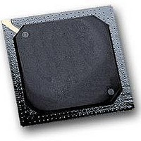
MPC564CZP40
Description
IC MPU 32BIT W/CODE COMP 388PBGA
Manufacturer
Freescale Semiconductor
Series
MPC5xxr
Specifications of MPC564CZP40
Core Processor
PowerPC
Core Size
32-Bit
Speed
40MHz
Connectivity
CAN, EBI/EMI, SCI, SPI, UART/USART
Peripherals
POR, PWM, WDT
Number Of I /o
56
Program Memory Size
512KB (512K x 8)
Program Memory Type
FLASH
Ram Size
32K x 8
Voltage - Supply (vcc/vdd)
2.5 V ~ 2.7 V
Data Converters
A/D 32x10b
Oscillator Type
External
Operating Temperature
-40°C ~ 85°C
Package / Case
388-BGA
Processor Series
MPC5xx
Core
PowerPC
Data Bus Width
32 bit
Data Ram Size
32 KB
Interface Type
CAN, JTAG, QSPI, SCI, SPI, UART
Maximum Clock Frequency
40 MHz
Number Of Programmable I/os
56
Number Of Timers
2
Operating Supply Voltage
0 V to 5 V
Maximum Operating Temperature
+ 85 C
Mounting Style
SMD/SMT
Minimum Operating Temperature
- 40 C
On-chip Adc
2 (10 bit, 32 Channel)
For Use With
MPC564EVB - KIT EVAL FOR MPC561/562/563/564
Lead Free Status / RoHS Status
Contains lead / RoHS non-compliant
Eeprom Size
-
Lead Free Status / Rohs Status
No
Available stocks
Company
Part Number
Manufacturer
Quantity
Price
Company:

Part Number:
MPC564CZP40
Manufacturer:
Freescale Semiconductor
Quantity:
10 000


Note: (T
Following are PPM timing diagrams.
G.21 MIOS Timing Characteristics
All MIOS output pins are slew rate controlled. Slew rate control circuitry adds 90 ns as minimum to the
output timing and 650 ns as a maximum. This slew rate is from 10% V
ns should be added for total 0 to V
Freescale Semiconductor
PPM_TSYNC
1
2
3
PPM_TX[0:1]
PPM_TCLK
PPM_TCLK
139 Rise Time
140 Fall Time
Nu
m
All AC timing is tested to the 2.6-V levels outlined in <XrefBlue>Table G.6 on page G-7.
Although the PPM permits frequencies of up to f
at frequencies above f
TC is defined to be the clock period.
A
= T
Input
Output –
2.6V PPM pads (PDMCR2[PPMV] = 0)
5V PPM pads (PDMCR2[PPMV] = 1)
Input
Output –
2.6V PPM pads (PDMCR2[PPMV] = 0)
5V PPM pads (PDMCR2[PPMV] = 1)
L
to T
H
, 50 pF Load on all Pins)
SYS
/8 for EMI/EMC reasons.
Figure G-45. PPM Data Transfer Timing (SPI Mode)
MPC561/MPC563 Reference Manual, Rev. 1.2
Table G-22. PPM Timing (continued)
DD
Rating
Figure G-44. PPM_TCLK Timing
slew rate.
SYS
/2, if the 5-V bus is selected the bus frequency should not be run
Symbol
DD
t
t
t
t
RO
FO
HI
FI
to 90% V
66-MHz Electrical Characteristics
Min
—
—
—
—
—
—
DD
, an additional 100
Max
15
15
1
7
1
7
Unit
µs
ns
ns
µs
ns
ns
G-59
Related parts for MPC564CZP40
Image
Part Number
Description
Manufacturer
Datasheet
Request
R

Part Number:
Description:
MPC5 1K0 5%
Manufacturer:
TE Connectivity
Datasheet:


Part Number:
Description:
MPC5 500R 5%
Manufacturer:
TE Connectivity
Datasheet:

Part Number:
Description:
MPC5 5K0 5%
Manufacturer:
Tyco Electronics
Datasheet:
Part Number:
Description:
MPC5 5R0 5%
Manufacturer:
Tyco Electronics
Datasheet:
Part Number:
Description:
MPC5 50K 5%
Manufacturer:
Tyco Electronics
Datasheet:
Part Number:
Description:
MPC5 1R0 5%
Manufacturer:
Tyco Electronics
Datasheet:

Part Number:
Description:
Manufacturer:
Freescale Semiconductor, Inc
Datasheet:
Part Number:
Description:
Manufacturer:
Freescale Semiconductor, Inc
Datasheet:
Part Number:
Description:
Manufacturer:
Freescale Semiconductor, Inc
Datasheet:
Part Number:
Description:
Manufacturer:
Freescale Semiconductor, Inc
Datasheet:
Part Number:
Description:
Manufacturer:
Freescale Semiconductor, Inc
Datasheet: