MPC564CZP40 Freescale Semiconductor, MPC564CZP40 Datasheet - Page 591
MPC564CZP40
Manufacturer Part Number
MPC564CZP40
Description
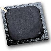
IC MPU 32BIT W/CODE COMP 388PBGA
Manufacturer
Freescale Semiconductor
Series
MPC5xxr
Specifications of MPC564CZP40
Core Processor
PowerPC
Core Size
32-Bit
Speed
40MHz
Connectivity
CAN, EBI/EMI, SCI, SPI, UART/USART
Peripherals
POR, PWM, WDT
Number Of I /o
56
Program Memory Size
512KB (512K x 8)
Program Memory Type
FLASH
Ram Size
32K x 8
Voltage - Supply (vcc/vdd)
2.5 V ~ 2.7 V
Data Converters
A/D 32x10b
Oscillator Type
External
Operating Temperature
-40°C ~ 85°C
Package / Case
388-BGA
Processor Series
MPC5xx
Core
PowerPC
Data Bus Width
32 bit
Data Ram Size
32 KB
Interface Type
CAN, JTAG, QSPI, SCI, SPI, UART
Maximum Clock Frequency
40 MHz
Number Of Programmable I/os
56
Number Of Timers
2
Operating Supply Voltage
0 V to 5 V
Maximum Operating Temperature
+ 85 C
Mounting Style
SMD/SMT
Minimum Operating Temperature
- 40 C
On-chip Adc
2 (10 bit, 32 Channel)
For Use With
MPC564EVB - KIT EVAL FOR MPC561/562/563/564
Lead Free Status / RoHS Status
Contains lead / RoHS non-compliant
Eeprom Size
-
Lead Free Status / Rohs Status
No
Available stocks
Company
Part Number
Manufacturer
Quantity
Price
Company:

Part Number:
MPC564CZP40
Manufacturer:
Freescale Semiconductor
Quantity:
10 000


The MCU system clock frequency (IMB3 system clock – f
QCLK is generated by a software selectable prescaler that divides f
conversion time to be maximized across f
waveform by setting the PRESCALER field in the QACR0 register.
When the value of PRESCALER > 0 the resulting frequency of QCLK is calculated using the following
formula:
The QADC64E requires that f
field is set to Zero, the resulting QCLK frequency is calculated to be:
Freescale Semiconductor
Prescaler Rate Selection
(from Control Register 0)
System Clock (F
Input Sample Time
(From CCW)
QUEUE 1 & 2 Timer
Mode Rate Selection
f
f
QCLK
QCLK
A change in the prescaler value while a conversion is in progress is likely to
corrupt the result from any conversion in progress. Therefore, any prescaler
write operation should be done only when both queues are in the disabled
modes.
= f
= f
SYSCLK
SYSCLK
SYS
)
Figure 14-23. QADC64E Clock Subsystem Functions
/ (PRESCALER + 1)
/ 2
SYSCLK
MPC561/MPC563 Reference Manual, Rev. 1.2
8
be at least twice f
SYSCLK
2 7
WARNING
2 8
. The software establishes the frequency of QCLK
2 9
2 10
Periodic / interval
Binary Counter
A/D Converter
State Machine
Timer Select
QCLK
2 11
2 12
SYSCLK
2 13
. Therefore if the value in the PRESCALER
2 14
( F
2 15
) is the basis of the QADC64E timing.
SYS
SYSCLK
2 16 2 17
QADC Clock
/ ÷2 to F
QADC CLOCK BLOCK
QADC64E Enhanced Mode Operation
thus allowing the A/D
Generate
Clock
SYS
2
/ ÷40 )
Periodic/interval
Trigger Event
for Q1 and Q2
SAR Control
SAR[9:0]
QCLK
14-49
Related parts for MPC564CZP40
Image
Part Number
Description
Manufacturer
Datasheet
Request
R

Part Number:
Description:
MPC5 1K0 5%
Manufacturer:
TE Connectivity
Datasheet:


Part Number:
Description:
MPC5 500R 5%
Manufacturer:
TE Connectivity
Datasheet:

Part Number:
Description:
MPC5 5K0 5%
Manufacturer:
Tyco Electronics
Datasheet:
Part Number:
Description:
MPC5 5R0 5%
Manufacturer:
Tyco Electronics
Datasheet:
Part Number:
Description:
MPC5 50K 5%
Manufacturer:
Tyco Electronics
Datasheet:
Part Number:
Description:
MPC5 1R0 5%
Manufacturer:
Tyco Electronics
Datasheet:

Part Number:
Description:
Manufacturer:
Freescale Semiconductor, Inc
Datasheet:
Part Number:
Description:
Manufacturer:
Freescale Semiconductor, Inc
Datasheet:
Part Number:
Description:
Manufacturer:
Freescale Semiconductor, Inc
Datasheet:
Part Number:
Description:
Manufacturer:
Freescale Semiconductor, Inc
Datasheet:
Part Number:
Description:
Manufacturer:
Freescale Semiconductor, Inc
Datasheet: