MPC564CZP40 Freescale Semiconductor, MPC564CZP40 Datasheet - Page 637
MPC564CZP40
Manufacturer Part Number
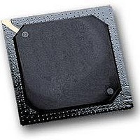
MPC564CZP40
Description
IC MPU 32BIT W/CODE COMP 388PBGA
Manufacturer
Freescale Semiconductor
Series
MPC5xxr
Specifications of MPC564CZP40
Core Processor
PowerPC
Core Size
32-Bit
Speed
40MHz
Connectivity
CAN, EBI/EMI, SCI, SPI, UART/USART
Peripherals
POR, PWM, WDT
Number Of I /o
56
Program Memory Size
512KB (512K x 8)
Program Memory Type
FLASH
Ram Size
32K x 8
Voltage - Supply (vcc/vdd)
2.5 V ~ 2.7 V
Data Converters
A/D 32x10b
Oscillator Type
External
Operating Temperature
-40°C ~ 85°C
Package / Case
388-BGA
Processor Series
MPC5xx
Core
PowerPC
Data Bus Width
32 bit
Data Ram Size
32 KB
Interface Type
CAN, JTAG, QSPI, SCI, SPI, UART
Maximum Clock Frequency
40 MHz
Number Of Programmable I/os
56
Number Of Timers
2
Operating Supply Voltage
0 V to 5 V
Maximum Operating Temperature
+ 85 C
Mounting Style
SMD/SMT
Minimum Operating Temperature
- 40 C
On-chip Adc
2 (10 bit, 32 Channel)
For Use With
MPC564EVB - KIT EVAL FOR MPC561/562/563/564
Lead Free Status / RoHS Status
Contains lead / RoHS non-compliant
Eeprom Size
-
Lead Free Status / Rohs Status
No
Available stocks
Company
Part Number
Manufacturer
Quantity
Price
Company:

Part Number:
MPC564CZP40
Manufacturer:
Freescale Semiconductor
Quantity:
10 000


15.6.1.2
SPCR1 enables the QSPI and specifies transfer delays. The CPU has read/write access to SPCR1, but the
QSPI has read access only to all bits except SPE. SPCR1 must be written last during initialization because
it contains SPE. The QSPI automatically clears this bit after it completes all serial transfers or when a mode
fault occurs. Writing a new value to SPCR1 while the QSPI is enabled disrupts operation.
Freescale Semiconductor
SRESET
Bits
8:15
1:7
0
Field
Addr
QSPI Control Register 1 (SPCR1)
DSCKL
Name
SPE
DTL
SPE
MSB
0
0
QSPI enable. Refer to Section 15.6.4.1, “Enabling, Disabling, and Halting the SPI.
0 = QSPI is disabled. QSPI pins can be used for general-purpose I/O.
1 = QSPI is enabled. Pins allocated by PQSPAR are controlled by the QSPI.
Delay before SCK. When the DSCK bit is set in a command RAM byte, this field determines the
length of the delay from PCS valid to SCK transition. The following equation determines the
actual delay before SCK:
where DSCKL equals is in the range of 1 to 127.
Refer to Section 15.6.5.3, “Delay Before Transfer for more information.
Length of delay after transfer. When the DT bit is set in a command RAM byte, this field
determines the length of the delay after a serial transfer. The following equation is used to
calculate the delay:
where DTL is in the range of 1 to 255.
A zero value for DTL causes a delay-after-transfer value of 8192 ÷ f
IMB3 clock).
Refer to Section 15.6.5.4, “Delay After Transfer for more information.
1
2
Figure 15-12. SPCR1 — QSPI Control Register
Table 15-14. Bits Per Transfer (continued)
MPC561/MPC563 Reference Manual, Rev. 1.2
3
Table 15-15. SPCR1 Bit Descriptions
000_0100
DSCKL
Bits[3:0]
1011
1100
1101
1110
1111
4
5
Delay after Transfer
PCS to SCK Delay
6
0x30 501A
Bits per Transfer
7
Description
11
12
13
14
15
8
=
=
9
32XDTL
---------------------- -
DSCKL
------------------- -
f
f
SYS
SYS
10
0000_0100
Queued Serial Multi-Channel Module
11
SYS
DTL
(204.8 µs with a 40-MHz
12
13
14
LSB
15
15-19
Related parts for MPC564CZP40
Image
Part Number
Description
Manufacturer
Datasheet
Request
R

Part Number:
Description:
MPC5 1K0 5%
Manufacturer:
TE Connectivity
Datasheet:


Part Number:
Description:
MPC5 500R 5%
Manufacturer:
TE Connectivity
Datasheet:

Part Number:
Description:
MPC5 5K0 5%
Manufacturer:
Tyco Electronics
Datasheet:
Part Number:
Description:
MPC5 5R0 5%
Manufacturer:
Tyco Electronics
Datasheet:
Part Number:
Description:
MPC5 50K 5%
Manufacturer:
Tyco Electronics
Datasheet:
Part Number:
Description:
MPC5 1R0 5%
Manufacturer:
Tyco Electronics
Datasheet:

Part Number:
Description:
Manufacturer:
Freescale Semiconductor, Inc
Datasheet:
Part Number:
Description:
Manufacturer:
Freescale Semiconductor, Inc
Datasheet:
Part Number:
Description:
Manufacturer:
Freescale Semiconductor, Inc
Datasheet:
Part Number:
Description:
Manufacturer:
Freescale Semiconductor, Inc
Datasheet:
Part Number:
Description:
Manufacturer:
Freescale Semiconductor, Inc
Datasheet: