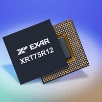
XRT75R12DIB-F Exar Corporation, XRT75R12DIB-F Datasheet - Page 105

XRT75R12DIB-F
Manufacturer Part Number
XRT75R12DIB-F
Description
Peripheral Drivers & Components (PCIs) 12 Channel 3.3V-5V temp -45 to 85C
Manufacturer
Exar Corporation
Datasheet
1.XRT75R12DIB-F.pdf
(133 pages)
Specifications of XRT75R12DIB-F
Maximum Operating Temperature
+ 85 C
Minimum Operating Temperature
- 40 C
Mounting Style
SMD/SMT
Operating Supply Voltage
3.3 V to 5 V
Package / Case
TBGA-420
Lead Free Status / RoHS Status
Lead free / RoHS Compliant
- Current page: 105 of 133
- Download datasheet (851Kb)
REV. 1.0.3
In the previous section, we described how a DS3 signal is asynchronously-mapped into SONET, and we also
defined "Mapping/De-mapping" jitter. In this section, we will describe how occurrences within the SONET
network will induce jitter/wander within the DS3 signal that is being transported across the SONET network.
In order to accomplish this, we will discuss the following topics in detail.
As mentioned earlier, the STS-1 SPE is not aligned to the STS-1 frame boundaries and is permitted to "float"
within the Envelope Capacity. As a consequence, the STS-1 SPE will often times "straddle" across two
consecutive STS-1 frames.
consecutive STS-1 frames.
A PTE that is receiving and terminating an STS-1 data-stream will perform the following tasks.
The H1 and H2 bytes are referred to (in the SONET standards) as the SPE Pointer Bytes. When these two
bytes are concatenated together in order to form a 16-bit word (with the H1 byte functioning as the "Most
Significant Byte") then the contents of the "lower" 10 bit-fields (within this 16-bit word) reflects the location of
the J1 byte within the Envelope Capacity of the incoming STS-1 data-stream.
illustration of the bit format of the H1 and H2 bytes, and indicates which bit-fields are used to reflect the
location of the J1 byte.
F
8.3
8.3.1
IGURE
The concept of an STS-1 SPE pointer
The concept of Pointer Adjustments
The causes of Pointer Adjustments
How Pointer Adjustments induce jitter/wander within a DS3 signal being transported by that SONET network.
It will acquire and maintain STS-1 frame synchronization with the incoming STS-1 data-stream.
Once the PTE has acquired STS-1 frame synchronization, then it will locate the J1 byte (e.g., the very byte
within the very next STS-1 SPE) within the Envelope Capacity by reading out the contents of the H1 and H2
bytes.
48. A
Jitter/Wander due to Pointer Adjustments
H1, H2
The Concept of an STS-1 SPE Pointer
TWELVE CHANNEL E3/DS3/STS-1 LINE INTERFACE UNIT WITH SONET DESYNCHRONIZER
Bytes
J1 Byte (1
N
I
LLUSTRATION OF AN
TOH
st
byte of SPE)
Figure 48
STS-1 FRAME N
STS-1 SPE
SPE can straddle across two STS-1 frames
presents an illustration of an STS-1 SPE straddling across two
STRADDLING ACROSS TWO CONSECUTIVE
101
J1 Byte (1
STS-1 FRAME N + 1
st
byte of next SPE)
Figure 49
STS-1
XRT75R12D
FRAMES
presents an
Related parts for XRT75R12DIB-F
Image
Part Number
Description
Manufacturer
Datasheet
Request
R

Part Number:
Description:
Twelve Channel E3/ds3/sts-1 Line Interface Unit With Jitter
Manufacturer:
Exar Corporation
Datasheet:

Part Number:
Description:
BiCMOS Fixed, Quad, Voltage Output, Single or Dual Supply 8-Bit Digital-to-Analog Converter
Manufacturer:
Exar Corporation
Datasheet:

Part Number:
Description:
Manufacturer:
Exar Corporation
Datasheet:

Part Number:
Description:
Voltage-Controlled Oscillator
Manufacturer:
Exar Corporation
Datasheet:

Part Number:
Description:
INTEGRATED LINE TRANSMITTER
Manufacturer:
Exar Corporation
Datasheet:

Part Number:
Description:
Monolithic Function Generator
Manufacturer:
Exar Corporation
Datasheet:

Part Number:
Description:
CMOS Microprocessor Compatible Double-Buffered 12-Bit Digital-to-Analog Converter
Manufacturer:
Exar Corporation
Datasheet:

Part Number:
Description:
CMOS 6 BIT HIGH SPEED ANALOG TO DIGITAL CONVERTER
Manufacturer:
Exar Corporation
Datasheet:

Part Number:
Description:
Manufacturer:
Exar Corporation
Datasheet:

Part Number:
Description:
Manufacturer:
Exar Corporation
Datasheet:

Part Number:
Description:
8-Channel, Voltage Output 10 MHz Input Bandwidth 8-Bit Multiplying DACs with Serial Digital Data Por
Manufacturer:
Exar Corporation
Datasheet:

Part Number:
Description:
15 V CMOS Multiplying10-Bit Digital-to-Analog Converter
Manufacturer:
Exar Corporation
Datasheet:

Part Number:
Description:
Monolithic Function Generator
Manufacturer:
Exar Corporation
Datasheet:


