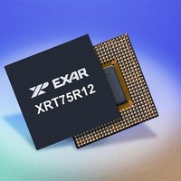
XRT75R12DIB-F Exar Corporation, XRT75R12DIB-F Datasheet - Page 63

XRT75R12DIB-F
Manufacturer Part Number
XRT75R12DIB-F
Description
Peripheral Drivers & Components (PCIs) 12 Channel 3.3V-5V temp -45 to 85C
Manufacturer
Exar Corporation
Datasheet
1.XRT75R12DIB-F.pdf
(133 pages)
Specifications of XRT75R12DIB-F
Maximum Operating Temperature
+ 85 C
Minimum Operating Temperature
- 40 C
Mounting Style
SMD/SMT
Operating Supply Voltage
3.3 V to 5 V
Package / Case
TBGA-420
Lead Free Status / RoHS Status
Lead free / RoHS Compliant
- Current page: 63 of 133
- Download datasheet (851Kb)
REV. 1.0.3
THE GLOBAL/CHIP-LEVEL REGISTERS
The register set, within the XRT75R12D contains ten global or chip-level registers. These registers control
operations in more than one channel or apply to the complete chip. This section will present detailed
information on the Global Registers.
REGISTER DESCRIPTION - GLOBAL REGISTERS
N
UMBER
Reserved
B
7,6
5
4
3
2
1
0
B
IT
IT
T
7
A
ABLE
DDRESS
0x00
0x08
0x80
0x88
0x60
0x61
0xE0
0xE1
0x6E
0x6F
TWELVE CHANNEL E3/DS3/STS-1 LINE INTERFACE UNIT WITH SONET DESYNCHRONIZER
TxON Ch 5
TxON Ch 4
TxON Ch 3
TxON Ch 2
TxON Ch 1
TxON Ch 0
Reserved
N
19: APS/R
AME
Reserved
B
IT
6
T
C
R
ABLE
CR128
CR136
CR224
CR225
CR110
OMMAND
CR111
EGISTER
EDUNDANCY
CR96
CR97
T
R/W
CR0
CR8
YPE
TxON Ch 5
18: L
B
R/W
Transmit Section ON - Channel n
This READ/WRITE bit-field is used to turn on or turn off the Transmit Driver associated
with Channel n. If the user turns on the Transmit Driver, then Channel n will transmit
DS3, E3 or STS-1 pulses on the line via the TTIP_n and TRING_ n output pins.
Conversely, if the user turns off the Transmit Driver, then the TTIP_n and TRING_n
output pins will be tri-stated.
0 - Shuts off the Transmit Driver associated with Channel n and tri-states the TTIP_n
and TRING_ n output pins.
1 - Turns on the Transmit Driver associated with Channel n.
N
IT
OTE
IST AND
5
: The master TxON control pin(pin # P4) must be in a high state (logic 1) for this
T
L
APSR
APSR
APST
APST
RANSMIT
CIE
CIS
CIE
CIS
ABEL
PN
VN
operation to turn on any channel.
A
TxON Ch 4
DDRESS
B
R/W
C
IT
ROM
ROM
T
R/W
R/W
R/W
R/W
R/W
R/W
R/O
R/O
ONTROL
4
YPE
L
59
OCATIONS OF
APS Transmit Redundancy Control Register 0-5
APS Receive Redundancy Control Register 0-5
APS Transmit Redundancy Control Register 6-11
APS Receive Redundancy Control Register 6-11
Channel 0-5 Interrupt Enable flags
Channel 0-5 Interrupt Status flags
Channel 6-11 Interrupt Enable flags
Channel 6-11 Interrupt Status flags
Device Part Number Register
Chip Revision/Version Number Register
TxON Ch 3
R
EGISTER
B
R/W
IT
3
D
ESCRIPTION
- CR0 (A
G
LOBAL
TxON Ch 2
R
B
R/W
EGISTER
IT
R
DDRESS
2
EGISTERS
N
AME
TxON Ch 1
L
OCATION
B
R/W
IT
1
XRT75R12D
= 0
TxON Ch 0
X
00)
B
R/W
IT
0
Related parts for XRT75R12DIB-F
Image
Part Number
Description
Manufacturer
Datasheet
Request
R

Part Number:
Description:
Twelve Channel E3/ds3/sts-1 Line Interface Unit With Jitter
Manufacturer:
Exar Corporation
Datasheet:

Part Number:
Description:
BiCMOS Fixed, Quad, Voltage Output, Single or Dual Supply 8-Bit Digital-to-Analog Converter
Manufacturer:
Exar Corporation
Datasheet:

Part Number:
Description:
Manufacturer:
Exar Corporation
Datasheet:

Part Number:
Description:
Voltage-Controlled Oscillator
Manufacturer:
Exar Corporation
Datasheet:

Part Number:
Description:
INTEGRATED LINE TRANSMITTER
Manufacturer:
Exar Corporation
Datasheet:

Part Number:
Description:
Monolithic Function Generator
Manufacturer:
Exar Corporation
Datasheet:

Part Number:
Description:
CMOS Microprocessor Compatible Double-Buffered 12-Bit Digital-to-Analog Converter
Manufacturer:
Exar Corporation
Datasheet:

Part Number:
Description:
CMOS 6 BIT HIGH SPEED ANALOG TO DIGITAL CONVERTER
Manufacturer:
Exar Corporation
Datasheet:

Part Number:
Description:
Manufacturer:
Exar Corporation
Datasheet:

Part Number:
Description:
Manufacturer:
Exar Corporation
Datasheet:

Part Number:
Description:
8-Channel, Voltage Output 10 MHz Input Bandwidth 8-Bit Multiplying DACs with Serial Digital Data Por
Manufacturer:
Exar Corporation
Datasheet:

Part Number:
Description:
15 V CMOS Multiplying10-Bit Digital-to-Analog Converter
Manufacturer:
Exar Corporation
Datasheet:

Part Number:
Description:
Monolithic Function Generator
Manufacturer:
Exar Corporation
Datasheet:


