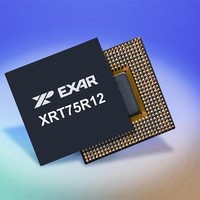
XRT75R12DIB-F Exar Corporation, XRT75R12DIB-F Datasheet - Page 27

XRT75R12DIB-F
Manufacturer Part Number
XRT75R12DIB-F
Description
Peripheral Drivers & Components (PCIs) 12 Channel 3.3V-5V temp -45 to 85C
Manufacturer
Exar Corporation
Datasheet
1.XRT75R12DIB-F.pdf
(133 pages)
Specifications of XRT75R12DIB-F
Maximum Operating Temperature
+ 85 C
Minimum Operating Temperature
- 40 C
Mounting Style
SMD/SMT
Operating Supply Voltage
3.3 V to 5 V
Package / Case
TBGA-420
Lead Free Status / RoHS Status
Lead free / RoHS Compliant
- Current page: 27 of 133
- Download datasheet (851Kb)
REV. 1.0.3
A Digital Loss of SIgnal (DLOS) condition occurs when a string of 175 ± 75 consecutive zeros occur on the line.
When the DLOS condition occurs, the DLOS_n bit is set to “1” in the status control register. DLOS condition is
cleared when the detected average pulse density is greater than 33% for 175 ± 75 pulses. Analog Loss of
Signal (ALOS) condition occurs when the amplitude of the incoming line signal is below the threshold as shown
in the
logical OR of the DLOS and ALOS states. When the RLOS condition occurs the RLOS_n output pin is toggled
“High” and the RLOS_n bit is set to “1” in the status control register.
For debugging purposes it is useful to disable the ALOS and/or DLOS detection. Writing a “1” to both
ALOSDIS_n and DLOSDIS_n bits disables the LOS detection on a per channel basis.
If the level of incoming line signal drops below the threshold as described in the ITU-T G.775 standard, the
LOS condition is detected. Loss of signal is defined as no transitions for 10 to 255 consecutive zeros. No
transitions is defined as a signal level between 15 and 35 dB below the normal. This is illustrated in
The LOS condition is cleared within 10 to 255 UI after restoration of the incoming line signal.
the LOS declaration and clearance conditions.
F
3.5
3.5.1
A
3.5.2
3.5.3
IGURE
PPLICATION
T
ABLE
STS-1
DS3
Table
8. L
LOS (Loss of Signal) Detector
3: T
DS3/STS-1 LOS Condition
Disabling ALOS/DLOS Detection
E3 LOS Condition:
TWELVE CHANNEL E3/DS3/STS-1 LINE INTERFACE UNIT WITH SONET DESYNCHRONIZER
3.The status of the ALOS condition is reflected in the ALOS_n status control register. RLOS is the
OSS
HE
REQEN S
ALOS (A
O
F
S
0
1
0
1
IGNAL
ETTING
NALOG
0 dB
-12 dB
-35dB
-15dB
D
EFINITION FOR
LOS) D
REQEN (DS3
ECLARATION AND
LOS Signal Must be Cleared
LOS Signal may be Cleared or Declared
LOS Signal Must be Declared
E3
AS PER
S
AND
IGNAL
STS-1 A
23
ITU-T G.775
L
EVEL TO
C
< 41mVpk
< 52mVpk
< 51mVpk
< 58mVpk
LEARANCE
D
EFECT
PPLICATIONS
D
ECLARE
Maximum Cable Loss for E3
T
HRESHOLDS FOR A GIVEN SETTING OF
ALOS
)
S
IGNAL
L
EVEL TO
> 102mVpk
> 117mVpk
> 114mVpk
> 133mVpk
D
XRT75R12D
EFECT
Figure 9
C
LEAR
Figure
ALOS
shows
8.
Related parts for XRT75R12DIB-F
Image
Part Number
Description
Manufacturer
Datasheet
Request
R

Part Number:
Description:
Twelve Channel E3/ds3/sts-1 Line Interface Unit With Jitter
Manufacturer:
Exar Corporation
Datasheet:

Part Number:
Description:
BiCMOS Fixed, Quad, Voltage Output, Single or Dual Supply 8-Bit Digital-to-Analog Converter
Manufacturer:
Exar Corporation
Datasheet:

Part Number:
Description:
Manufacturer:
Exar Corporation
Datasheet:

Part Number:
Description:
Voltage-Controlled Oscillator
Manufacturer:
Exar Corporation
Datasheet:

Part Number:
Description:
INTEGRATED LINE TRANSMITTER
Manufacturer:
Exar Corporation
Datasheet:

Part Number:
Description:
Monolithic Function Generator
Manufacturer:
Exar Corporation
Datasheet:

Part Number:
Description:
CMOS Microprocessor Compatible Double-Buffered 12-Bit Digital-to-Analog Converter
Manufacturer:
Exar Corporation
Datasheet:

Part Number:
Description:
CMOS 6 BIT HIGH SPEED ANALOG TO DIGITAL CONVERTER
Manufacturer:
Exar Corporation
Datasheet:

Part Number:
Description:
Manufacturer:
Exar Corporation
Datasheet:

Part Number:
Description:
Manufacturer:
Exar Corporation
Datasheet:

Part Number:
Description:
8-Channel, Voltage Output 10 MHz Input Bandwidth 8-Bit Multiplying DACs with Serial Digital Data Por
Manufacturer:
Exar Corporation
Datasheet:

Part Number:
Description:
15 V CMOS Multiplying10-Bit Digital-to-Analog Converter
Manufacturer:
Exar Corporation
Datasheet:

Part Number:
Description:
Monolithic Function Generator
Manufacturer:
Exar Corporation
Datasheet:


