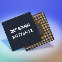
XRT75R12DIB-F Exar Corporation, XRT75R12DIB-F Datasheet - Page 69

XRT75R12DIB-F
Manufacturer Part Number
XRT75R12DIB-F
Description
Peripheral Drivers & Components (PCIs) 12 Channel 3.3V-5V temp -45 to 85C
Manufacturer
Exar Corporation
Datasheet
1.XRT75R12DIB-F.pdf
(133 pages)
Specifications of XRT75R12DIB-F
Maximum Operating Temperature
+ 85 C
Minimum Operating Temperature
- 40 C
Mounting Style
SMD/SMT
Operating Supply Voltage
3.3 V to 5 V
Package / Case
TBGA-420
Lead Free Status / RoHS Status
Lead free / RoHS Compliant
- Current page: 69 of 133
- Download datasheet (851Kb)
REV. 1.0.3
Register - CR225 (Address Location = 0xE1)
Register - CR110 (Address Location = 0x6E)
Reserved Reserved
B
N
B
UMBER
IT
7, 6
B
IT
5
4
3
2
1
0
B
N
7 - 0
R/O
IT
7
IT
0
UMBER
T
7
ABLE
TWELVE CHANNEL E3/DS3/STS-1 LINE INTERFACE UNIT WITH SONET DESYNCHRONIZER
Channel 10 Interrupt Status
Channel 11 Interrupt Status
Channel 9 Interrupt Status
Channel 8 Interrupt Status
Channel 7 Interrupt Status
Channel 6 Interrupt Status
B
IT
T
26: C
Part Number ID
6
ABLE
B
R/O
Reserved
IT
N
Value
HANNEL
Interrupt Status
1
27: D
N
AME
Channel 11
6
AME
B
R/O
IT
EVICE
5
L
EVEL
B
/P
R/O
IT
0
ART
I
Interrupt Status
NTERRUPT
5
T
R/O
YPE
Channel 10
N
T
B
R/O
R/O
UMBER
YPE
IT
4
Part Number ID Value
B
D
S
Channel n Interrupt Status Bit:
This READ-ONLY bit-field indicates whether the XRT75R12D has a
pending Channel n-related interrupt that is awaiting service. The last
six channels are serviced through this location and the other six at
address 0x61. These two registers are used by the Host to identify the
source channel of an active interrupt.
0 - Indicates that there is NO Channel n-related Interrupt awaiting ser-
vice.
1 - Indicates that there is at least one Channel n-related Interrupt
awaiting service. In this case, the user's Interrupt Service routine
should be written such that the Microprocessor will now proceed to
read out the contents of the Source Level Interrupt Status Register -
Channel n (Address Locations = 0xn2) to determine the exact source
of the interrupt request.
N
R/O
V
IT
EFAULT
TATUS
R
1
0x58
OTE
ALUE
EGISTER
4
Interrupt Status
: Once this bit-field is set to "1", it will not be cleared back to "0"
Channel 9
until the user has read out the contents of the Source-Level
Interrupt Status Register bit, that corresponds to the interrupt
request channel.
65
R
B
R/O
Part Number ID Value:
This READ-ONLY register contains a unique value for the
XRT75R12D. This value will always be 0x58.
EGISTER
IT
- CR110 (A
3
B
R/O
IT
1
3
- CR225 (A
Interrupt Status
Channel 8
DDRESS
B
R/O
IT
D
B
2
ESCRIPTION
R/O
IT
0
DDRESS
D
2
L
ESCRIPTION
OCATION
Interrupt Status
Channel 7
L
B
OCATION
R/O
IT
B
R/O
= 0
IT
1
0
1
X
6E)
XRT75R12D
= 0
Interrupt Status
X
Channel 6
E1)
B
R/O
B
R/O
IT
IT
0
0
0
Related parts for XRT75R12DIB-F
Image
Part Number
Description
Manufacturer
Datasheet
Request
R

Part Number:
Description:
Twelve Channel E3/ds3/sts-1 Line Interface Unit With Jitter
Manufacturer:
Exar Corporation
Datasheet:

Part Number:
Description:
BiCMOS Fixed, Quad, Voltage Output, Single or Dual Supply 8-Bit Digital-to-Analog Converter
Manufacturer:
Exar Corporation
Datasheet:

Part Number:
Description:
Manufacturer:
Exar Corporation
Datasheet:

Part Number:
Description:
Voltage-Controlled Oscillator
Manufacturer:
Exar Corporation
Datasheet:

Part Number:
Description:
INTEGRATED LINE TRANSMITTER
Manufacturer:
Exar Corporation
Datasheet:

Part Number:
Description:
Monolithic Function Generator
Manufacturer:
Exar Corporation
Datasheet:

Part Number:
Description:
CMOS Microprocessor Compatible Double-Buffered 12-Bit Digital-to-Analog Converter
Manufacturer:
Exar Corporation
Datasheet:

Part Number:
Description:
CMOS 6 BIT HIGH SPEED ANALOG TO DIGITAL CONVERTER
Manufacturer:
Exar Corporation
Datasheet:

Part Number:
Description:
Manufacturer:
Exar Corporation
Datasheet:

Part Number:
Description:
Manufacturer:
Exar Corporation
Datasheet:

Part Number:
Description:
8-Channel, Voltage Output 10 MHz Input Bandwidth 8-Bit Multiplying DACs with Serial Digital Data Por
Manufacturer:
Exar Corporation
Datasheet:

Part Number:
Description:
15 V CMOS Multiplying10-Bit Digital-to-Analog Converter
Manufacturer:
Exar Corporation
Datasheet:

Part Number:
Description:
Monolithic Function Generator
Manufacturer:
Exar Corporation
Datasheet:


