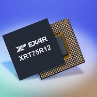
XRT75R12DIB-F Exar Corporation, XRT75R12DIB-F Datasheet - Page 97

XRT75R12DIB-F
Manufacturer Part Number
XRT75R12DIB-F
Description
Peripheral Drivers & Components (PCIs) 12 Channel 3.3V-5V temp -45 to 85C
Manufacturer
Exar Corporation
Datasheet
1.XRT75R12DIB-F.pdf
(133 pages)
Specifications of XRT75R12DIB-F
Maximum Operating Temperature
+ 85 C
Minimum Operating Temperature
- 40 C
Mounting Style
SMD/SMT
Operating Supply Voltage
3.3 V to 5 V
Package / Case
TBGA-420
Lead Free Status / RoHS Status
Lead free / RoHS Compliant
- Current page: 97 of 133
- Download datasheet (851Kb)
REV. 1.0.3
Although the role of the H1, H2 and H3 bytes will be discussed in much greater detail in
Wander due to Pointer Adjustments” on page
is two-fold.
In general, the Envelope Capacity Bytes are any bytes (within an STS-1 frame) that exist outside of the TOH
bytes. In short, the Envelope Capacity contains the STS-1 SPE (Synchronous Payload Envelope). In fact,
every single byte that exists within the Envelope Capacity also exists within the STS-1 SPE. The only
difference that exists between the "Envelope Capacity" as defined in
STS-1 SPE is that the Envelope Capacity is aligned with the STS-1 framing boundaries and the TOH bytes;
whereas the STS-1 SPE is NOT aligned with the STS-1 framing boundaries, nor the TOH bytes.
The STS-1 SPE is an "87 byte column x 9 row" data-structure (which is the exact same size as is the Envelope
Capacity) that is permitted to "float" within the "Envelope Capacity". As a consequence, the STS-1 SPE (within
an STS-1 data-stream) will typically straddle across an STS-1 frame boundary.
As mentioned above, the STS-1 SPE is an 87 byte column x 9 row structure. The very first column within the
STS-1 SPE consists of some overhead bytes which are known as the "Path Overhead" (or POH) bytes. The
remaining portions of the STS-1 SPE is available for "user" data. The Byte Structure of the STS-1 SPE is
presented below in
F
8.2.1.1.2
8.2.1.1.3
IGURE
To permit a given PTE (Path Terminating Equipment) that is receiving an STS-1 data to be able to locate the
STS-1 SPE (Synchronous Payload Envelope) within the Envelope Capacity of this incoming STS-1 data
stream and,
To inform a given PTE whenever Pointer Adjustment and NDF (New Data Flag) events occur within the
incoming STS-1 data-stream.
41. T
TWELVE CHANNEL E3/DS3/STS-1 LINE INTERFACE UNIT WITH SONET DESYNCHRONIZER
HE
The Envelope Capacity Bytes within an STS-1 Frame
The Byte Structure of the STS-1 SPE
B
9 Rows
YTE
Figure
-F
ORMAT OF THE
42.
D10
A1
B1
D1
H1
B2
D4
D7
D10
S1
A1
D1
H1
D4
D7
B1
B2
S1
3 Byte Columns
D11
M0
A2
D2
H2
K1
D5
D8
D11
E1
M0
A2
D2
H2
K1
D5
D8
E1
TOH
WITHIN AN
D12
C1
D3
H3
K2
D6
D9
D12
F1
E2
D3
H3
K2
D6
D9
C1
F1
E2
101. For now, we will simply state that the role of these bytes
The TOH Bytes
93
STS-1 F
Envelope Capacity
Envelope Capacity
RAME
87 Byte Columns
Bytes
Bytes
Figure 40
and
Figure 41
“Section 8.3, Jitter/
XRT75R12D
above and the
Related parts for XRT75R12DIB-F
Image
Part Number
Description
Manufacturer
Datasheet
Request
R

Part Number:
Description:
Twelve Channel E3/ds3/sts-1 Line Interface Unit With Jitter
Manufacturer:
Exar Corporation
Datasheet:

Part Number:
Description:
BiCMOS Fixed, Quad, Voltage Output, Single or Dual Supply 8-Bit Digital-to-Analog Converter
Manufacturer:
Exar Corporation
Datasheet:

Part Number:
Description:
Manufacturer:
Exar Corporation
Datasheet:

Part Number:
Description:
Voltage-Controlled Oscillator
Manufacturer:
Exar Corporation
Datasheet:

Part Number:
Description:
INTEGRATED LINE TRANSMITTER
Manufacturer:
Exar Corporation
Datasheet:

Part Number:
Description:
Monolithic Function Generator
Manufacturer:
Exar Corporation
Datasheet:

Part Number:
Description:
CMOS Microprocessor Compatible Double-Buffered 12-Bit Digital-to-Analog Converter
Manufacturer:
Exar Corporation
Datasheet:

Part Number:
Description:
CMOS 6 BIT HIGH SPEED ANALOG TO DIGITAL CONVERTER
Manufacturer:
Exar Corporation
Datasheet:

Part Number:
Description:
Manufacturer:
Exar Corporation
Datasheet:

Part Number:
Description:
Manufacturer:
Exar Corporation
Datasheet:

Part Number:
Description:
8-Channel, Voltage Output 10 MHz Input Bandwidth 8-Bit Multiplying DACs with Serial Digital Data Por
Manufacturer:
Exar Corporation
Datasheet:

Part Number:
Description:
15 V CMOS Multiplying10-Bit Digital-to-Analog Converter
Manufacturer:
Exar Corporation
Datasheet:

Part Number:
Description:
Monolithic Function Generator
Manufacturer:
Exar Corporation
Datasheet:


