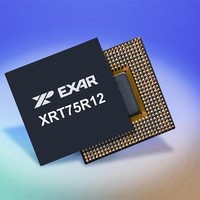
XRT75R12DIB-F Exar Corporation, XRT75R12DIB-F Datasheet - Page 84

XRT75R12DIB-F
Manufacturer Part Number
XRT75R12DIB-F
Description
Peripheral Drivers & Components (PCIs) 12 Channel 3.3V-5V temp -45 to 85C
Manufacturer
Exar Corporation
Datasheet
1.XRT75R12DIB-F.pdf
(133 pages)
Specifications of XRT75R12DIB-F
Maximum Operating Temperature
+ 85 C
Minimum Operating Temperature
- 40 C
Mounting Style
SMD/SMT
Operating Supply Voltage
3.3 V to 5 V
Package / Case
TBGA-420
Lead Free Status / RoHS Status
Lead free / RoHS Compliant
- Current page: 84 of 133
- Download datasheet (851Kb)
C
XRT75R12D
TWELVE CHANNEL E3/DS3/STS-1 LINE INTERFACE UNIT WITH SONET DESYNCHRONIZER
B
HANNEL
IT
B
7 - 6
N
T
IT
UMBER
5
ABLE
7
Reserved
C
ONTROL
35: XRT75R12D R
PRBS Enable
B
Reserved
R
IT
N
EGISTER
6
AME
PRBS Enable
- C
EGISTER
Ch_n
B
R/W
HANNEL N
IT
T
R/W
5
YPE
MAP
PRBS Generator and Receiver Enable - Channel_n:
This READ/WRITE bit-field is used to enable or disable the PRBS Generator
and Receiver within a given Channel of the XRT75R12D.
If the user enables the PRBS Generator and Receiver, then the following will
happen.
0 - Disables both the PRBS Generator and PRBS Receiver within the corre-
sponding channel.
1 - Enables both the PRBS Generator and PRBS Receiver within the corre-
sponding channel.
N
OTES
A
1. The PRBS Generator (which resides within the Transmit Section of
2. The PRBS Receiver (which resides within the Receive Section of the
DDRESS
RLB_n
SHOWING
B
1. To check and monitor PRBS Bit Errors, DR (Dual Rail) mode will be
2. If the user enables the PRBS Generator and PRBS Receiver, the
3. The system must provide an accurate and stable data-rate clock to
R/W
the Channel) will begin to generate an unframed, 2^15-1 PRBS
Pattern (for DS3 and STS-1 applications) and an unframed, 2^23-1
PRBS Pattern (for E3 applications).
Channel) will now be enabled and will begin to search the incoming
data for the above-mentioned PRBS patterns.
:
IT
4
over-ridden and Single Rail mode forced for the duration of this
mode. This will configure the RNEG/LCV_n output pin to function
as a PRBS Error Indicator. All errors will be flagged on this pin.
The errors will also be accumulated in the 16 bit Error counter for
the channel.
Channel will ignore the data that is being accepted from the
System-side Equipment (via the TxPOS_n and TxNEG_n input
pins) and will overwrite this outbound data with the PRBS Pattern.
the TxClk_n pin during this operation.
L
80
OCATION
C
HANNEL
LLB_n
B
R/W
IT
3
= 0
C
XM
ONTROL
6 (
D
ESCRIPTION
M
E3_n
B
R/W
= 0-5 & 8-D)
R
IT
EGISTERS
2
STS-1/DS3_n
(CC_
B
R/W
IT
1
N
)
(
N
= [0:11])
SR/DR_n
REV. 1.0.3
B
R/W
IT
0
Related parts for XRT75R12DIB-F
Image
Part Number
Description
Manufacturer
Datasheet
Request
R

Part Number:
Description:
Twelve Channel E3/ds3/sts-1 Line Interface Unit With Jitter
Manufacturer:
Exar Corporation
Datasheet:

Part Number:
Description:
BiCMOS Fixed, Quad, Voltage Output, Single or Dual Supply 8-Bit Digital-to-Analog Converter
Manufacturer:
Exar Corporation
Datasheet:

Part Number:
Description:
Manufacturer:
Exar Corporation
Datasheet:

Part Number:
Description:
Voltage-Controlled Oscillator
Manufacturer:
Exar Corporation
Datasheet:

Part Number:
Description:
INTEGRATED LINE TRANSMITTER
Manufacturer:
Exar Corporation
Datasheet:

Part Number:
Description:
Monolithic Function Generator
Manufacturer:
Exar Corporation
Datasheet:

Part Number:
Description:
CMOS Microprocessor Compatible Double-Buffered 12-Bit Digital-to-Analog Converter
Manufacturer:
Exar Corporation
Datasheet:

Part Number:
Description:
CMOS 6 BIT HIGH SPEED ANALOG TO DIGITAL CONVERTER
Manufacturer:
Exar Corporation
Datasheet:

Part Number:
Description:
Manufacturer:
Exar Corporation
Datasheet:

Part Number:
Description:
Manufacturer:
Exar Corporation
Datasheet:

Part Number:
Description:
8-Channel, Voltage Output 10 MHz Input Bandwidth 8-Bit Multiplying DACs with Serial Digital Data Por
Manufacturer:
Exar Corporation
Datasheet:

Part Number:
Description:
15 V CMOS Multiplying10-Bit Digital-to-Analog Converter
Manufacturer:
Exar Corporation
Datasheet:

Part Number:
Description:
Monolithic Function Generator
Manufacturer:
Exar Corporation
Datasheet:


