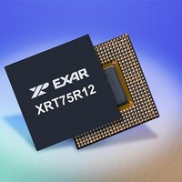
XRT75R12DIB-F Exar Corporation, XRT75R12DIB-F Datasheet - Page 109

XRT75R12DIB-F
Manufacturer Part Number
XRT75R12DIB-F
Description
Peripheral Drivers & Components (PCIs) 12 Channel 3.3V-5V temp -45 to 85C
Manufacturer
Exar Corporation
Datasheet
1.XRT75R12DIB-F.pdf
(133 pages)
Specifications of XRT75R12DIB-F
Maximum Operating Temperature
+ 85 C
Minimum Operating Temperature
- 40 C
Mounting Style
SMD/SMT
Operating Supply Voltage
3.3 V to 5 V
Package / Case
TBGA-420
Lead Free Status / RoHS Status
Lead free / RoHS Compliant
- Current page: 109 of 133
- Download datasheet (851Kb)
REV. 1.0.3
Figure 52
the "I" bits designated.
N
During the STS-1 frame that follows the "Byte-Stuffing" event
The "I" bits (within the "pointer-word") will be set back to their normal value; and the contents of the H1 and H2
bytes will be incremented by "1".
If f1 > f2
If frequency f1 is greater than f2, then this means that the STS-1 data is being clocked into the "Slip Buffer" at
a faster rate than is being clocked out. In this case, the "Slip Buffer" will start to fill up. Whenever this occurs,
a typical strategy is to delete (e.g., negative-stuff) a byte from the Slip Buffer. The purpose of this "negative-
stuffing" is to compensate for the frequency differences between f1 and f2; and to attempt to keep the "Slip
Buffer" at a somewhat constant fill-level.
N
Negative-Stuffing and Pointer-Decrementing in a SONET Network
Whenever this "byte negative-stuffing" occurs then the following other things occur within the STS-1 data-
stream.
During the STS-1 frame that contains the "Negative Byte-Stuffing" Event
F
BYTES
b. The "Transmitting" Network Equipment will notify the remote terminal of this byte-stuffing event, by invert-
OTE
OTE
IGURE
b. The remote PTE must be notified of the occurrence of these "negative-stuffing" events. Further, the
a. The "negative-stuffed" byte must not be simply discarded. In other words, it must somehow also be
a. The "Negative-Stuffed" byte will be inserted into the H3 byte position. Whenever an SPE data byte is
ing certain bits within the "pointer word" (within the H1 and H2 bytes) that are referred to as "I" bits.
: At this time the "I" bits are inverted in order to denote that an "incrementing" pointer adjustment event is currently
: This byte, which is being "un-stuffed" does carry valuable information for the user (e.g., this byte is typically a
)
transmitted to the remote PTE with the remainder of the SPE data.
remote PTE must know where to obtain this "negative-stuffed" byte.
inserted into the H3 byte position (which is ordinarily an unused byte), the number of bytes that will exist
between the H3 byte and the J1 byte within the very next SPE will be reduced by 1 byte. As a
consequence, in this case, the J1 byte (and in-turn, the rest of the SPE) will now be "byte-shifted"
towards the H3 byte position.
occurring.
payload byte). Therefore, whenever this negative stuffing occurs, two things must happen.
WITH THE
52. A
presents an illustration of the bit-format within the 16-bit word (consist of the H1 and H2 bytes) with
TWELVE CHANNEL E3/DS3/STS-1 LINE INTERFACE UNIT WITH SONET DESYNCHRONIZER
N
MSB
N
I
LLUSTRATION OF THE
"I"
BITS DESIGNATED
N
N
H1 Byte
N
S
B
IT
F
S
ORMAT WITHIN THE
I
D
105
10 Bit Pointer Expression
I
16-
D
BIT WORD
I
H2 Byte
D
(
CONSISTING OF THE
I
D
I
LSB
D
XRT75R12D
H1
AND
H2
Related parts for XRT75R12DIB-F
Image
Part Number
Description
Manufacturer
Datasheet
Request
R

Part Number:
Description:
Twelve Channel E3/ds3/sts-1 Line Interface Unit With Jitter
Manufacturer:
Exar Corporation
Datasheet:

Part Number:
Description:
BiCMOS Fixed, Quad, Voltage Output, Single or Dual Supply 8-Bit Digital-to-Analog Converter
Manufacturer:
Exar Corporation
Datasheet:

Part Number:
Description:
Manufacturer:
Exar Corporation
Datasheet:

Part Number:
Description:
Voltage-Controlled Oscillator
Manufacturer:
Exar Corporation
Datasheet:

Part Number:
Description:
INTEGRATED LINE TRANSMITTER
Manufacturer:
Exar Corporation
Datasheet:

Part Number:
Description:
Monolithic Function Generator
Manufacturer:
Exar Corporation
Datasheet:

Part Number:
Description:
CMOS Microprocessor Compatible Double-Buffered 12-Bit Digital-to-Analog Converter
Manufacturer:
Exar Corporation
Datasheet:

Part Number:
Description:
CMOS 6 BIT HIGH SPEED ANALOG TO DIGITAL CONVERTER
Manufacturer:
Exar Corporation
Datasheet:

Part Number:
Description:
Manufacturer:
Exar Corporation
Datasheet:

Part Number:
Description:
Manufacturer:
Exar Corporation
Datasheet:

Part Number:
Description:
8-Channel, Voltage Output 10 MHz Input Bandwidth 8-Bit Multiplying DACs with Serial Digital Data Por
Manufacturer:
Exar Corporation
Datasheet:

Part Number:
Description:
15 V CMOS Multiplying10-Bit Digital-to-Analog Converter
Manufacturer:
Exar Corporation
Datasheet:

Part Number:
Description:
Monolithic Function Generator
Manufacturer:
Exar Corporation
Datasheet:


