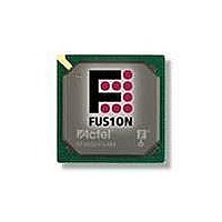
AFS250-FGG256 Actel, AFS250-FGG256 Datasheet - Page 255

AFS250-FGG256
Manufacturer Part Number
AFS250-FGG256
Description
FPGA - Field Programmable Gate Array 250K System Gates
Manufacturer
Actel
Datasheet
1.AFS600-PQG208.pdf
(330 pages)
Specifications of AFS250-FGG256
Processor Series
AFS250
Core
IP Core
Maximum Operating Frequency
1098.9 MHz
Number Of Programmable I/os
114
Data Ram Size
36864
Supply Voltage (max)
1.575 V
Maximum Operating Temperature
+ 70 C
Minimum Operating Temperature
0 C
Development Tools By Supplier
AFS-Eval-Kit, AFS-BRD600, FlashPro 3, FlashPro Lite, Silicon-Explorer II, Silicon-Sculptor 3, SI-EX-TCA
Mounting Style
SMD/SMT
Supply Voltage (min)
1.425 V
Number Of Gates
250 K
Package / Case
FPBGA-256
Lead Free Status / RoHS Status
Lead free / RoHS Compliant
Available stocks
Company
Part Number
Manufacturer
Quantity
Price
Company:
Part Number:
AFS250-FGG256
Manufacturer:
Actel
Quantity:
135
Company:
Part Number:
AFS250-FGG256
Manufacturer:
ACTEL
Quantity:
6 800
Company:
Part Number:
AFS250-FGG256I
Manufacturer:
Microsemi SoC
Quantity:
10 000
- Current page: 255 of 330
- Download datasheet (13Mb)
Table 3-5 • FPGA Programming, Storage, and Operating Limits
I/O Power-Up and Supply Voltage Thresholds for Power-On Reset
(Commercial and Industrial)
Sophisticated power-up management circuitry is designed into every Fusion device. These circuits
ensure easy transition from the powered off state to the powered up state of the device. The many
different supplies can power up in any sequence with minimized current spikes or surges. In addition, the
I/O will be in a known state through the power-up sequence. The basic principle is shown in
on page
There are five regions to consider during power-up.
Fusion I/Os are activated only if ALL of the following three conditions are met:
V
Ramping up: 0.6 V < trip_point_up < 1.2 V
Ramping down: 0.5 V < trip_point_down < 1.1 V
V
Ramping up: 0.6 V < trip_point_up < 1.1 V
Ramping down: 0.5 V < trip_point_down < 1 V
VCC and VCCI ramp-up trip points are about 100 mV higher than ramp-down trip points. This specifically
built-in hysteresis prevents undesirable power-up oscillations and current surges. Note the following:
Internal Power-Up Activation Sequence
PLL Behavior at Brownout Condition
Actel recommends using monotonic power supplies or voltage regulators to ensure proper power-up
behavior. Power ramp-up should be monotonic at least until VCC and VCCPLX exceed brownout
activation levels. The V
for more details).
When PLL power supply voltage and/or VCC levels drop below the VCC brownout levels
(0.75 V ± 0.25 V), the PLL output lock signal goes low and/or the output clock is lost.
Product
Grade
Commercial
Industrial
CCI
CC
1. VCC and VCCI are above the minimum specified trip points
2. VCCI > VCC – 0.75 V (typical).
3. Chip is in the operating mode.
•
•
1. Core
2. Input buffers
3. Output buffers, after 200 ns delay from input buffer activation
Trip Point:
Trip Point:
During programming, I/Os become tristated and weakly pulled up to VCCI.
JTAG supply, PLL power supplies, and charge pump VPUMP supply have no influence on I/O
behavior.
3-6.
Min. T
Min. T
Min. T
Temperature
Min. T
Storage
CC
J
J
J
activation level is specified as 1.1 V worst-case (see
J
= –40°C
= 100°C
= 85°C
= 0°C
FPGA/FlashROM
FPGA/FlashROM
Embedded Flash
Embedded Flash
R e v i s i o n 1
Element
Grade Programming
Actel Fusion Family of Mixed Signal FPGAs
(Figure
< 10,000
< 15,000
< 10,000
< 15,000
< 1,000
< 1,000
Cycles
500
500
3-1).
Figure 3-1 on page 3-6
Retention
20 years
20 years
10 years
20 years
20 years
10 years
5 years
5 years
Figure 3-1
3 -5
Related parts for AFS250-FGG256
Image
Part Number
Description
Manufacturer
Datasheet
Request
R

Part Number:
Description:
FPGA 256/I�/Fusion Voltage: 1.5, 1.8, 2.5, 3.3 Mixed Voltage
Manufacturer:
Actel
Datasheet:

Part Number:
Description:
FPGA - Field Programmable Gate Array 250K System Gates
Manufacturer:
Actel
Datasheet:

Part Number:
Description:
MCU, MPU & DSP Development Tools Silicon Sculptor Programming Mod
Manufacturer:
Actel

Part Number:
Description:
MCU, MPU & DSP Development Tools InSystem Programming ProASICPLUS Devices
Manufacturer:
Actel

Part Number:
Description:
Programming Socket Adapters & Emulators PQ160 Module
Manufacturer:
Actel

Part Number:
Description:
Programming Socket Adapters & Emulators Axcelerator Adap Module Kit
Manufacturer:
Actel

Part Number:
Description:
Programming Socket Adapters & Emulators Evaluation
Manufacturer:
Actel

Part Number:
Description:
Programming Socket Adapters & Emulators AFDX Solutions
Manufacturer:
Actel

Part Number:
Description:
Programming Socket Adapters & Emulators SILICON SCULPTOR ADAPTER MODULE
Manufacturer:
Actel
Datasheet:

Part Number:
Description:
Programming Socket Adapters & Emulators Axcelerator Adap Module Kit
Manufacturer:
Actel

Part Number:
Description:
Programming Socket Adapters & Emulators Evaluation
Manufacturer:
Actel

Part Number:
Description:
Programming Socket Adapters & Emulators Silicon Sculptor Software
Manufacturer:
Actel

Part Number:
Description:
Programming Socket Adapters & Emulators InSystem Programming ProASICPLUS Devices
Manufacturer:
Actel


