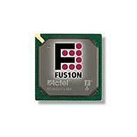
AFS250-FGG256 Actel, AFS250-FGG256 Datasheet - Page 37

AFS250-FGG256
Manufacturer Part Number
AFS250-FGG256
Description
FPGA - Field Programmable Gate Array 250K System Gates
Manufacturer
Actel
Datasheet
1.AFS600-PQG208.pdf
(330 pages)
Specifications of AFS250-FGG256
Processor Series
AFS250
Core
IP Core
Maximum Operating Frequency
1098.9 MHz
Number Of Programmable I/os
114
Data Ram Size
36864
Supply Voltage (max)
1.575 V
Maximum Operating Temperature
+ 70 C
Minimum Operating Temperature
0 C
Development Tools By Supplier
AFS-Eval-Kit, AFS-BRD600, FlashPro 3, FlashPro Lite, Silicon-Explorer II, Silicon-Sculptor 3, SI-EX-TCA
Mounting Style
SMD/SMT
Supply Voltage (min)
1.425 V
Number Of Gates
250 K
Package / Case
FPBGA-256
Lead Free Status / RoHS Status
Lead free / RoHS Compliant
Available stocks
Company
Part Number
Manufacturer
Quantity
Price
Company:
Part Number:
AFS250-FGG256
Manufacturer:
Actel
Quantity:
135
Company:
Part Number:
AFS250-FGG256
Manufacturer:
ACTEL
Quantity:
6 800
Company:
Part Number:
AFS250-FGG256I
Manufacturer:
Microsemi SoC
Quantity:
10 000
- Current page: 37 of 330
- Download datasheet (13Mb)
Crystal Oscillator
The Crystal Oscillator (XTLOSC) is source that generates the clock from an external crystal. The output
of XTLOSC CLKOUT signal can be selected as an input to the PLL. Refer to
Circuits" section
(RTC is running and 1.5 V is not present).
In normal operation, the internal FPGA_EN signal is '1' as long as 1.5 V is present for VCC. As such,
the internal enable signal, XTL_EN, for Crystal Oscillator is enabled since FPGA_EN is asserted. The
XTL_MODE has the option of using MODE or RTC_MODE, depending on SELMODE.
During Standby, 1.5 V is not available, as such, and FPGA_EN is '0'. SELMODE must be asserted in
order for XTL_EN to be enabled; hence XTL_MODE relies on RTC_MODE. SELMODE and RTC_MODE
must be connected to RTCXTLSEL and RTCXTLMODE from the AB respectively for correct operation
during Standby (refer to the
description).
The Crystal Oscillator can be configured in one of four modes:
In RC network mode, the XTAL1 pin is connected to an RC circuit, as shown in
pin should be left floating. The RC value can be chosen based on
between 32 KHz and 4 MHz. The RC network mode can also accommodate an external clock source on
XTAL1 instead of an RC circuit.
In Low gain, Medium gain, and High gain, an external crystal component or ceramic resonator can be
added onto XTAL1 and XTAL2, as shown in
Note:
Figure 2-17 • XTLOSC Macro
•
•
•
•
RC network, 32 KHz to 4 MHz
Low gain, 32 to 200 KHz
Medium gain, 0.20 to 2.0 MHz
High gain, 2.0 to 20.0 MHz
*Internal signal—does not exist in macro.
for more details. The XTLOSC can operate in normal operations and Standby mode
MODE[1:0]
RTC_MODE[1:0]
FPGA_EN*
SELMODE
XT LOSC
XT L
"Real-Time Counter System" section on page 2-33
0
1
Figure
R e v i s i o n 1
2-17.
XTL_MODE*
XTL_EN*
Actel Fusion Family of Mixed Signal FPGAs
Figure 2-18
C LKOU T
for any desired frequency
Figure
"Clock Conditioning
2-17. The XTAL2
for a detailed
2- 21
Related parts for AFS250-FGG256
Image
Part Number
Description
Manufacturer
Datasheet
Request
R

Part Number:
Description:
FPGA 256/I�/Fusion Voltage: 1.5, 1.8, 2.5, 3.3 Mixed Voltage
Manufacturer:
Actel
Datasheet:

Part Number:
Description:
FPGA - Field Programmable Gate Array 250K System Gates
Manufacturer:
Actel
Datasheet:

Part Number:
Description:
MCU, MPU & DSP Development Tools Silicon Sculptor Programming Mod
Manufacturer:
Actel

Part Number:
Description:
MCU, MPU & DSP Development Tools InSystem Programming ProASICPLUS Devices
Manufacturer:
Actel

Part Number:
Description:
Programming Socket Adapters & Emulators PQ160 Module
Manufacturer:
Actel

Part Number:
Description:
Programming Socket Adapters & Emulators Axcelerator Adap Module Kit
Manufacturer:
Actel

Part Number:
Description:
Programming Socket Adapters & Emulators Evaluation
Manufacturer:
Actel

Part Number:
Description:
Programming Socket Adapters & Emulators AFDX Solutions
Manufacturer:
Actel

Part Number:
Description:
Programming Socket Adapters & Emulators SILICON SCULPTOR ADAPTER MODULE
Manufacturer:
Actel
Datasheet:

Part Number:
Description:
Programming Socket Adapters & Emulators Axcelerator Adap Module Kit
Manufacturer:
Actel

Part Number:
Description:
Programming Socket Adapters & Emulators Evaluation
Manufacturer:
Actel

Part Number:
Description:
Programming Socket Adapters & Emulators Silicon Sculptor Software
Manufacturer:
Actel

Part Number:
Description:
Programming Socket Adapters & Emulators InSystem Programming ProASICPLUS Devices
Manufacturer:
Actel


