OM13005,598 NXP Semiconductors, OM13005,598 Datasheet - Page 302
OM13005,598
Manufacturer Part Number
OM13005,598
Description
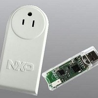
BOARD EVAL EM773 METER US PLUG
Manufacturer
NXP Semiconductors
Type
Other Power Managementr
Specifications of OM13005,598
Design Resources
Plug Meter Schematics, Gerber Files USB Dongle Schematics, Gerber Files
Main Purpose
Power Management, Energy/Power Meter
Embedded
Yes, MCU, 32-Bit
Utilized Ic / Part
EM773FHN33,551
Interface Type
USB
Maximum Operating Temperature
+ 150 C
Operating Supply Voltage
1.8 V to 3.6 V
Product
Power Management Development Tools
Lead Free Status / RoHS Status
Lead free / RoHS Compliant
Primary Attributes
-
Secondary Attributes
-
Lead Free Status / Rohs Status
Lead free / RoHS Compliant
For Use With/related Products
EM773, OL2381
Other names
568-6680


NXP Semiconductors
21.6 Contents
Chapter 1: EM773 Introductory information
1.1
1.2
1.3
Chapter 2: EM773 Memory mapping
2.1
Chapter 3: EM773 System configuration
3.1
3.2
3.3
3.4
3.4.1
3.4.2
3.4.3
3.4.4
3.4.5
3.4.6
3.4.7
3.4.8
3.4.9
3.4.10
3.4.11
3.4.12
3.4.13
3.4.14
3.4.15
3.4.16
3.4.17
3.4.18
3.4.19
3.4.20
3.4.21
3.4.22
3.4.23
3.4.24
3.4.25
3.4.26
3.4.27
3.4.28
3.4.29
3.4.30
3.4.31
3.4.32
Chapter 4: EM773 PMU (Power Management Unit)
4.1
4.2
4.2.1
4.2.2
UM10415
User manual
Introduction . . . . . . . . . . . . . . . . . . . . . . . . . . . . 3
Features . . . . . . . . . . . . . . . . . . . . . . . . . . . . . . . 3
Ordering information . . . . . . . . . . . . . . . . . . . . . 4
Memory map. . . . . . . . . . . . . . . . . . . . . . . . . . . . 7
Introduction . . . . . . . . . . . . . . . . . . . . . . . . . . . . 9
Pin description . . . . . . . . . . . . . . . . . . . . . . . . . . 9
Clocking and power control . . . . . . . . . . . . . . . 9
Register description . . . . . . . . . . . . . . . . . . . . 10
Introduction . . . . . . . . . . . . . . . . . . . . . . . . . . . 39
Register description . . . . . . . . . . . . . . . . . . . . 39
System memory remap register . . . . . . . . . . . 12
Peripheral reset control register . . . . . . . . . . . 12
System PLL control register . . . . . . . . . . . . . . 13
System PLL status register. . . . . . . . . . . . . . . 13
System oscillator control register . . . . . . . . . . 13
Watchdog oscillator control register . . . . . . . . 14
Internal resonant crystal control register. . . . . 15
System reset status register . . . . . . . . . . . . . . 16
System PLL clock source select register . . . . 16
System PLL clock source update enable register.
17
Main clock source select register . . . . . . . . . . 17
Main clock source update enable register . . . 17
System AHB clock divider register . . . . . . . . . 18
System AHB clock control register . . . . . . . . . 18
SPI0 clock divider register . . . . . . . . . . . . . . . 20
UART clock divider register . . . . . . . . . . . . . . 20
WDT clock source select register . . . . . . . . . . 20
WDT clock source update enable register . . . 21
WDT clock divider register . . . . . . . . . . . . . . . 21
CLKOUT clock source select register. . . . . . . 21
CLKOUT clock source update enable register 22
CLKOUT clock divider register . . . . . . . . . . . . 22
POR captured PIO status register 0 . . . . . . . . 22
POR captured PIO status register 1 . . . . . . . . 23
BOD control register . . . . . . . . . . . . . . . . . . . . 23
System tick counter calibration register . . . . . 24
Start logic edge control register 0 . . . . . . . . . . 24
Start logic signal enable register 0 . . . . . . . . . 25
Start logic reset register 0 . . . . . . . . . . . . . . . . 25
Start logic status register 0 . . . . . . . . . . . . . . 25
Deep-sleep mode configuration register. . . . . 26
Wake-up configuration register. . . . . . . . . . . . 27
Power control register. . . . . . . . . . . . . . . . . . . 39
General purpose registers 0 to 3 . . . . . . . . . . 40
All information provided in this document is subject to legal disclaimers.
Rev. 1 — 10 September 2010
1.4
1.5
3.4.33
3.4.34
3.5
3.6
3.7
3.7.1
3.7.1.1
3.7.2
3.7.2.1
3.7.2.2
3.7.2.3
3.7.3
3.7.3.1
3.7.3.2
3.7.3.3
3.7.4
3.7.4.1
3.7.4.2
3.7.4.3
3.8
3.8.1
3.8.2
3.8.3
3.9
3.9.1
3.9.2
3.9.3
3.9.4
3.9.4.1
3.9.4.2
3.10
4.2.3
4.3
Chapter 21: EM773 Supplementary information
Block diagram . . . . . . . . . . . . . . . . . . . . . . . . . . 5
ARM Cortex-M0 processor . . . . . . . . . . . . . . . . 6
Reset . . . . . . . . . . . . . . . . . . . . . . . . . . . . . . . . 30
Brown-out detection . . . . . . . . . . . . . . . . . . . . 30
Power management . . . . . . . . . . . . . . . . . . . . 30
Deep-sleep mode details . . . . . . . . . . . . . . . . 34
System PLL functional description . . . . . . . . 35
Flash memory access. . . . . . . . . . . . . . . . . . . 38
Functional description . . . . . . . . . . . . . . . . . . 40
Power-down configuration register . . . . . . . . 28
Device ID register . . . . . . . . . . . . . . . . . . . . . 29
Active mode . . . . . . . . . . . . . . . . . . . . . . . . . . 30
Power configuration in Active mode. . . . . . . . 31
Sleep mode . . . . . . . . . . . . . . . . . . . . . . . . . . 31
Power configuration in Sleep mode . . . . . . . . 31
Programming Sleep mode . . . . . . . . . . . . . . . 31
Wake-up from Sleep mode . . . . . . . . . . . . . . 32
Deep-sleep mode. . . . . . . . . . . . . . . . . . . . . . 32
Power configuration in Deep-sleep mode . . . 32
Programming Deep-sleep mode . . . . . . . . . . 32
Wake-up from Deep-sleep mode . . . . . . . . . . 33
Deep power-down mode . . . . . . . . . . . . . . . . 33
Power configuration in Deep power-down mode .
33
Programming Deep power-down mode . . . . . 33
Wake-up from Deep power-down mode . . . . 34
IRC oscillator . . . . . . . . . . . . . . . . . . . . . . . . . 34
Start logic . . . . . . . . . . . . . . . . . . . . . . . . . . . . 34
Using the general purpose counter/timers to
create a self-wake-up event. . . . . . . . . . . . . . 34
Lock detector . . . . . . . . . . . . . . . . . . . . . . . . . 36
Power-down control . . . . . . . . . . . . . . . . . . . . 36
Divider ratio programming . . . . . . . . . . . . . . . 36
Post divider . . . . . . . . . . . . . . . . . . . . . . . . . . . 36
Feedback divider . . . . . . . . . . . . . . . . . . . . . . . 36
Changing the divider values. . . . . . . . . . . . . . . 36
Frequency selection. . . . . . . . . . . . . . . . . . . . 36
Normal mode . . . . . . . . . . . . . . . . . . . . . . . . . 37
Power-down mode . . . . . . . . . . . . . . . . . . . . . 37
General purpose register 4 . . . . . . . . . . . . . . 40
UM10415
© NXP B.V. 2010. All rights reserved.
302 of 310
Related parts for OM13005,598
Image
Part Number
Description
Manufacturer
Datasheet
Request
R

Part Number:
Description:
NXP Semiconductors designed the LPC2420/2460 microcontroller around a 16-bit/32-bitARM7TDMI-S CPU core with real-time debug interfaces that include both JTAG andembedded trace
Manufacturer:
NXP Semiconductors
Datasheet:

Part Number:
Description:
NXP Semiconductors designed the LPC2458 microcontroller around a 16-bit/32-bitARM7TDMI-S CPU core with real-time debug interfaces that include both JTAG andembedded trace
Manufacturer:
NXP Semiconductors
Datasheet:
Part Number:
Description:
NXP Semiconductors designed the LPC2468 microcontroller around a 16-bit/32-bitARM7TDMI-S CPU core with real-time debug interfaces that include both JTAG andembedded trace
Manufacturer:
NXP Semiconductors
Datasheet:
Part Number:
Description:
NXP Semiconductors designed the LPC2470 microcontroller, powered by theARM7TDMI-S core, to be a highly integrated microcontroller for a wide range ofapplications that require advanced communications and high quality graphic displays
Manufacturer:
NXP Semiconductors
Datasheet:
Part Number:
Description:
NXP Semiconductors designed the LPC2478 microcontroller, powered by theARM7TDMI-S core, to be a highly integrated microcontroller for a wide range ofapplications that require advanced communications and high quality graphic displays
Manufacturer:
NXP Semiconductors
Datasheet:
Part Number:
Description:
The Philips Semiconductors XA (eXtended Architecture) family of 16-bit single-chip microcontrollers is powerful enough to easily handle the requirements of high performance embedded applications, yet inexpensive enough to compete in the market for hi
Manufacturer:
NXP Semiconductors
Datasheet:
Part Number:
Description:
The XA-S3 device is a member of Philips Semiconductors? XA(eXtended Architecture) family of high performance 16-bitsingle-chip microcontrollers
Manufacturer:
NXP Semiconductors
Datasheet:

Part Number:
Description:
The NXP BlueStreak LH75401/LH75411 family consists of two low-cost 16/32-bit System-on-Chip (SoC) devices
Manufacturer:
NXP Semiconductors
Datasheet:
Part Number:
Description:
The NXP LPC3130/3131 combine an 180 MHz ARM926EJ-S CPU core, high-speed USB2
Manufacturer:
NXP Semiconductors
Datasheet:
Part Number:
Description:
The NXP LPC3141 combine a 270 MHz ARM926EJ-S CPU core, High-speed USB 2
Manufacturer:
NXP Semiconductors
Part Number:
Description:
The NXP LPC3143 combine a 270 MHz ARM926EJ-S CPU core, High-speed USB 2
Manufacturer:
NXP Semiconductors

Part Number:
Description:
The NXP LPC3152 combines an 180 MHz ARM926EJ-S CPU core, High-speed USB 2
Manufacturer:
NXP Semiconductors
Part Number:
Description:
The NXP LPC3154 combines an 180 MHz ARM926EJ-S CPU core, High-speed USB 2
Manufacturer:
NXP Semiconductors

Part Number:
Description:
Standard level N-channel enhancement mode Field-Effect Transistor (FET) in a plastic package using NXP High-Performance Automotive (HPA) TrenchMOS technology
Manufacturer:
NXP Semiconductors
Datasheet: