OM13005,598 NXP Semiconductors, OM13005,598 Datasheet - Page 73
OM13005,598
Manufacturer Part Number
OM13005,598
Description
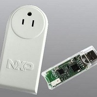
BOARD EVAL EM773 METER US PLUG
Manufacturer
NXP Semiconductors
Type
Other Power Managementr
Specifications of OM13005,598
Design Resources
Plug Meter Schematics, Gerber Files USB Dongle Schematics, Gerber Files
Main Purpose
Power Management, Energy/Power Meter
Embedded
Yes, MCU, 32-Bit
Utilized Ic / Part
EM773FHN33,551
Interface Type
USB
Maximum Operating Temperature
+ 150 C
Operating Supply Voltage
1.8 V to 3.6 V
Product
Power Management Development Tools
Lead Free Status / RoHS Status
Lead free / RoHS Compliant
Primary Attributes
-
Secondary Attributes
-
Lead Free Status / Rohs Status
Lead free / RoHS Compliant
For Use With/related Products
EM773, OL2381
Other names
568-6680


NXP Semiconductors
9.5 Clocking and power control
9.6 Register description
Table 89.
UM10415
User manual
Name
U0RBR
U0THR
U0DLL
U0DLM
U0IER
U0IIR
U0FCR
U0LCR
U0MCR
U0LSR
U0MSR
U0SCR
U0ACR
-
U0FDR
-
Register overview: UART (base address: 0x4000 8000)
Access Address
RO
WO
R/W
R/W
R/W
RO
WO
R/W
R/W
RO
RO
R/W
R/W
-
R/W
-
The UART block is gated by the AHBCLKCTRL register (see
UART clock, which is used by the UART baud rate generator, is controlled by the
UARTCLKDIV register (see
The UART_PCLK can be disabled in the UARTCLKDIV register (see
UART block can be disabled through the System AHB clock control register bit 12 (see
Table
Remark: The UART pins must be configured in the corresponding IOCON registers
before the UART clocks are enabled.
The UART contains registers organized as shown in
Bit (DLAB) is contained in U0LCR[7] and enables access to the Divisor Latches.
offset
0x000
0x000
0x000
0x004
0x004
0x008
0x008
0x00C
0x010
0x014
0x018
0x01C
0x020
0x024
0x028
0x02C
17) for power savings.
Description
Receiver Buffer Register. Contains the next received character
to be read.
Transmit Holding Register. The next character to be transmitted
is written here.
Divisor Latch LSB. Least significant byte of the baud rate
divisor value. The full divisor is used to generate a baud rate
from the fractional rate divider.
Divisor Latch MSB. Most significant byte of the baud rate
divisor value. The full divisor is used to generate a baud rate
from the fractional rate divider.
Interrupt Enable Register. Contains individual interrupt enable
bits for the 7 potential UART interrupts.
Interrupt ID Register. Identifies which interrupt(s) are pending.
FIFO Control Register. Controls UART FIFO usage and modes. 0x00
Line Control Register. Contains controls for frame formatting
and break generation.
Modem control register
Line Status Register. Contains flags for transmit and receive
status, including line errors.
Modem status register
Scratch Pad Register. Eight-bit temporary storage for software. 0x00
Auto-baud Control Register. Contains controls for the
auto-baud feature.
Reserved
Fractional Divider Register. Generates a clock input for the
baud rate divider.
Reserved
All information provided in this document is subject to legal disclaimers.
Rev. 1 — 10 September 2010
Chapter 9: EM773 Universal Asynchronous Transmitter (UART)
Table
19).
Table
89. The Divisor Latch Access
Table
17). The peripheral
Table
UM10415
-
-
Reset
Value
NA
NA
0x01
0x00
0x00
0x01
0x00
0x00
0x60
0x00
0x00
0x10
© NXP B.V. 2010. All rights reserved.
19) and the
[1]
Notes
when
DLAB=0
when
DLAB=0
when
DLAB=1
when
DLAB=1
when
DLAB=0
-
-
-
-
-
-
-
-
-
-
-
73 of 310
Related parts for OM13005,598
Image
Part Number
Description
Manufacturer
Datasheet
Request
R

Part Number:
Description:
NXP Semiconductors designed the LPC2420/2460 microcontroller around a 16-bit/32-bitARM7TDMI-S CPU core with real-time debug interfaces that include both JTAG andembedded trace
Manufacturer:
NXP Semiconductors
Datasheet:

Part Number:
Description:
NXP Semiconductors designed the LPC2458 microcontroller around a 16-bit/32-bitARM7TDMI-S CPU core with real-time debug interfaces that include both JTAG andembedded trace
Manufacturer:
NXP Semiconductors
Datasheet:
Part Number:
Description:
NXP Semiconductors designed the LPC2468 microcontroller around a 16-bit/32-bitARM7TDMI-S CPU core with real-time debug interfaces that include both JTAG andembedded trace
Manufacturer:
NXP Semiconductors
Datasheet:
Part Number:
Description:
NXP Semiconductors designed the LPC2470 microcontroller, powered by theARM7TDMI-S core, to be a highly integrated microcontroller for a wide range ofapplications that require advanced communications and high quality graphic displays
Manufacturer:
NXP Semiconductors
Datasheet:
Part Number:
Description:
NXP Semiconductors designed the LPC2478 microcontroller, powered by theARM7TDMI-S core, to be a highly integrated microcontroller for a wide range ofapplications that require advanced communications and high quality graphic displays
Manufacturer:
NXP Semiconductors
Datasheet:
Part Number:
Description:
The Philips Semiconductors XA (eXtended Architecture) family of 16-bit single-chip microcontrollers is powerful enough to easily handle the requirements of high performance embedded applications, yet inexpensive enough to compete in the market for hi
Manufacturer:
NXP Semiconductors
Datasheet:
Part Number:
Description:
The XA-S3 device is a member of Philips Semiconductors? XA(eXtended Architecture) family of high performance 16-bitsingle-chip microcontrollers
Manufacturer:
NXP Semiconductors
Datasheet:

Part Number:
Description:
The NXP BlueStreak LH75401/LH75411 family consists of two low-cost 16/32-bit System-on-Chip (SoC) devices
Manufacturer:
NXP Semiconductors
Datasheet:
Part Number:
Description:
The NXP LPC3130/3131 combine an 180 MHz ARM926EJ-S CPU core, high-speed USB2
Manufacturer:
NXP Semiconductors
Datasheet:
Part Number:
Description:
The NXP LPC3141 combine a 270 MHz ARM926EJ-S CPU core, High-speed USB 2
Manufacturer:
NXP Semiconductors
Part Number:
Description:
The NXP LPC3143 combine a 270 MHz ARM926EJ-S CPU core, High-speed USB 2
Manufacturer:
NXP Semiconductors

Part Number:
Description:
The NXP LPC3152 combines an 180 MHz ARM926EJ-S CPU core, High-speed USB 2
Manufacturer:
NXP Semiconductors
Part Number:
Description:
The NXP LPC3154 combines an 180 MHz ARM926EJ-S CPU core, High-speed USB 2
Manufacturer:
NXP Semiconductors

Part Number:
Description:
Standard level N-channel enhancement mode Field-Effect Transistor (FET) in a plastic package using NXP High-Performance Automotive (HPA) TrenchMOS technology
Manufacturer:
NXP Semiconductors
Datasheet: