OM13006,598 NXP Semiconductors, OM13006,598 Datasheet - Page 249
OM13006,598
Manufacturer Part Number
OM13006,598
Description
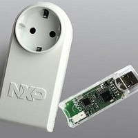
BOARD EVAL EM773 METER EU PLUG
Manufacturer
NXP Semiconductors
Type
Other Power Managementr
Specifications of OM13006,598
Design Resources
Plug Meter Schematics, Gerber Files USB Dongle Schematics, Gerber Files
Main Purpose
Power Management, Energy/Power Meter
Embedded
Yes, MCU, 32-Bit
Utilized Ic / Part
EM773FHN33,551
Interface Type
USB
Maximum Operating Temperature
+ 150 C
Operating Supply Voltage
1.8 V to 3.6 V
Product
Power Management Development Tools
Lead Free Status / RoHS Status
Lead free / RoHS Compliant
Primary Attributes
-
Secondary Attributes
-
Lead Free Status / Rohs Status
Lead free / RoHS Compliant
For Use With/related Products
EM773, OL2381
Other names
568-6681


NXP Semiconductors
UM10415
User manual
Fig 60. ASR #3
31
20.4.3.3.1 ASR
20.4.3.3.2 LSR
20.4.3.3 Shift Operations
Remark: When you update the PC with a BX, BLX, or POP instruction, bit[0] of any
address must be 1 for correct execution. This is because this bit indicates the destination
instruction set, and the Cortex-M0 processor only supports Thumb instructions. When a
BL or BLX instruction writes the value of bit[0] into the LR it is automatically assigned the
value 1.
Register shift operations move the bits in a register left or right by a specified number of
bits, the shift length. Register shift can be performed directly by the instructions ASR,
LSR, LSL, and ROR and the result is written to a destination register.The permitted shift
lengths depend on the shift type and the instruction, see the individual instruction
description. If the shift length is 0, no shift occurs. Register shift operations update the
carry flag except when the specified shift length is 0. The following sub-sections describe
the various shift operations and how they affect the carry flag. In these descriptions, Rm is
the register containing the value to be shifted, and n is the shift length.
Arithmetic shift right by n bits moves the left-hand 32 -n bits of the register Rm, to the right
by n places, into the right-hand 32 -n bits of the result, and it copies the original bit[31] of
the register into the left-hand n bits of the result. See
You can use the ASR operation to divide the signed value in the register Rm by 2
the result being rounded towards negative-infinity.
When the instruction is ASRS the carry flag is updated to the last bit shifted out, bit[n-1], of
the register Rm.
Remark:
Logical shift right by n bits moves the left-hand 32-n bits of the register Rm, to the right by
n places, into the right-hand 32 -n bits of the result, and it sets the left-hand n bits of the
result to 0. See
•
•
If n is 32 or more, then all the bits in the result are set to the value of bit[31] of Rm.
If n is 32 or more and the carry flag is updated, it is updated to the value of bit[31] of
Rm.
All information provided in this document is subject to legal disclaimers.
Figure
Rev. 1 — 10 September 2010
61.
...
Chapter 20: Appendix EM773 ARM Cortex-M0 reference
Figure
5
20–60.
4
3
2
UM10415
© NXP B.V. 2010. All rights reserved.
1 0
Carry
Flag
249 of 310
n
, with
Related parts for OM13006,598
Image
Part Number
Description
Manufacturer
Datasheet
Request
R

Part Number:
Description:
NXP Semiconductors designed the LPC2420/2460 microcontroller around a 16-bit/32-bitARM7TDMI-S CPU core with real-time debug interfaces that include both JTAG andembedded trace
Manufacturer:
NXP Semiconductors
Datasheet:

Part Number:
Description:
NXP Semiconductors designed the LPC2458 microcontroller around a 16-bit/32-bitARM7TDMI-S CPU core with real-time debug interfaces that include both JTAG andembedded trace
Manufacturer:
NXP Semiconductors
Datasheet:
Part Number:
Description:
NXP Semiconductors designed the LPC2468 microcontroller around a 16-bit/32-bitARM7TDMI-S CPU core with real-time debug interfaces that include both JTAG andembedded trace
Manufacturer:
NXP Semiconductors
Datasheet:
Part Number:
Description:
NXP Semiconductors designed the LPC2470 microcontroller, powered by theARM7TDMI-S core, to be a highly integrated microcontroller for a wide range ofapplications that require advanced communications and high quality graphic displays
Manufacturer:
NXP Semiconductors
Datasheet:
Part Number:
Description:
NXP Semiconductors designed the LPC2478 microcontroller, powered by theARM7TDMI-S core, to be a highly integrated microcontroller for a wide range ofapplications that require advanced communications and high quality graphic displays
Manufacturer:
NXP Semiconductors
Datasheet:
Part Number:
Description:
The Philips Semiconductors XA (eXtended Architecture) family of 16-bit single-chip microcontrollers is powerful enough to easily handle the requirements of high performance embedded applications, yet inexpensive enough to compete in the market for hi
Manufacturer:
NXP Semiconductors
Datasheet:
Part Number:
Description:
The XA-S3 device is a member of Philips Semiconductors? XA(eXtended Architecture) family of high performance 16-bitsingle-chip microcontrollers
Manufacturer:
NXP Semiconductors
Datasheet:

Part Number:
Description:
The NXP BlueStreak LH75401/LH75411 family consists of two low-cost 16/32-bit System-on-Chip (SoC) devices
Manufacturer:
NXP Semiconductors
Datasheet:
Part Number:
Description:
The NXP LPC3130/3131 combine an 180 MHz ARM926EJ-S CPU core, high-speed USB2
Manufacturer:
NXP Semiconductors
Datasheet:
Part Number:
Description:
The NXP LPC3141 combine a 270 MHz ARM926EJ-S CPU core, High-speed USB 2
Manufacturer:
NXP Semiconductors
Part Number:
Description:
The NXP LPC3143 combine a 270 MHz ARM926EJ-S CPU core, High-speed USB 2
Manufacturer:
NXP Semiconductors

Part Number:
Description:
The NXP LPC3152 combines an 180 MHz ARM926EJ-S CPU core, High-speed USB 2
Manufacturer:
NXP Semiconductors
Part Number:
Description:
The NXP LPC3154 combines an 180 MHz ARM926EJ-S CPU core, High-speed USB 2
Manufacturer:
NXP Semiconductors

Part Number:
Description:
Standard level N-channel enhancement mode Field-Effect Transistor (FET) in a plastic package using NXP High-Performance Automotive (HPA) TrenchMOS technology
Manufacturer:
NXP Semiconductors
Datasheet: