MOD5272-100IR NetBurner Inc, MOD5272-100IR Datasheet - Page 132
MOD5272-100IR
Manufacturer Part Number
MOD5272-100IR
Description
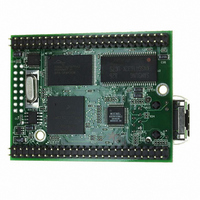
PROCESSOR MODULE FLASH MOD5272
Manufacturer
NetBurner Inc
Type
Controllers & Processorsr
Datasheets
1.MOD5272-100IR.pdf
(2 pages)
2.MOD5272-100IR.pdf
(3 pages)
3.MOD5272-100IR.pdf
(550 pages)
Specifications of MOD5272-100IR
Module/board Type
Processor Module
Ethernet Connection Type
10/100 Ethernet Port RJ-45
Operating Voltage
3.3 V
Product
Modules
Lead Free Status / RoHS Status
Lead free / RoHS Compliant
For Use With/related Products
MOD5272
For Use With
528-1001 - KIT DEVELOP NETWORK FOR MOD5272
Lead Free Status / Rohs Status
Lead free / RoHS Compliant
Other names
528-1008


Programming Model
1
Table 5-8 describes CSR fields.
5-10
DRc[4–0]
31–28
23–20
19–17
Bit 7 is reserved for Motorola use and must be written as a zero.
Bit
27
26
25
24
16
15
14
Reset
Reset
R/W
Field
Field MAP TRC EMU
R/W R/W R/W R/W
1
BSTAT Breakpoint status. Provides read-only status information concerning hardware breakpoints. BSTAT
Name
BKPT
HALT
TRG
MAP
FOF
HRL
TRC
IPW
—
31
15
0
is cleared by a TDR write or by a CSR read when either a level-2 breakpoint is triggered or a
level-1 breakpoint is triggered and the level-2 breakpoint is disabled.
0000 No breakpoints enabled
0001 Waiting for level-1 breakpoint
0010 Level-1 breakpoint triggered
0101 Waiting for level-2 breakpoint
0110 Level-2 breakpoint triggered
Fault-on-fault. If FOF is set, a catastrophic halt occurred and forced entry into BDM. FOF is cleared
whenever CSR is read.
Hardware breakpoint trigger. If TRG is set, a hardware breakpoint halted the processor core and
forced entry into BDM. Reset, the debug
Processor halt. If HALT is set, the processor executed a HALT and forced entry into BDM. Reset,
the debug
Breakpoint assert. If BKPT is set, BKPT was asserted, forcing the processor into BDM. Reset, the
debug
Hardware revision level. Indicates the level of debug module functionality. An emulator could use
this information to identify the level of functionality supported.
0000 Initial debug functionality (Revision A) (this is the only valid value for the MCF5272)
Reserved, should be cleared.
Inhibit processor writes. Setting IPW inhibits processor-initiated writes to the debug module’s
programming model registers. IPW can be modified only by commands from the external
development system.
Force processor references in emulator mode.
0 All emulator-mode references are mapped into supervisor code and data spaces.
1 The processor maps all references while in emulator mode to a special address space, TT = 10,
Force emulation mode on trace exception. If TRC = 1, the processor enters emulator mode when a
trace exception occurs. If TRC=0, the processor enters supervisor mode.
14
0
BSTAT
TM = 101 or 110.
0000
R
Figure 5-7. Configuration/Status Register (CSR)
GO
13
0
command, or reading CSR clear BKPT.
GO
28
12
command, or reading CSR clear HALT.
DDC
R/W
Table 5-8. CSR Field Descriptions
00
FOF TRG HALT BKPT
27
11
R
0
UHE
R/W
MCF5272 User’s Manual
26
10
R
0
0
25
R
0
9
BTB
R/W
00
GO
24
R
0
8
Description
0x00
command, or reading CSR clear TRG.
—
23
R
0
7
1
NPL
R/W R/W R/W
6
0
0000
HRL
R
IPI
0
5
SSM
20
0
4
19
0
3
—
—
0
0000
—
—
MOTOROLA
17
0
IPW
R/W
16
0
0
Related parts for MOD5272-100IR
Image
Part Number
Description
Manufacturer
Datasheet
Request
R

Part Number:
Description:
Ethernet Modules & Development Tools MOD5272 Processor Board
Manufacturer:
NetBurner Inc
Datasheet:
Part Number:
Description:
Ethernet Modules & Development Tools MOD5272 Industrial Temperature
Manufacturer:
NetBurner Inc
Part Number:
Description:
Ethernet Modules & Development Tools MOD5272 MODULE
Manufacturer:
NetBurner Inc
Datasheet:

Part Number:
Description:
PROCESSOR MODULE FLASH
Manufacturer:
NetBurner Inc
Datasheet:

Part Number:
Description:
Ethernet Modules & Development Tools 32Bit 62MHz Core Module 50Pin DIP
Manufacturer:
NetBurner Inc
Datasheet:

Part Number:
Description:
BOARD SERIAL-ETHERNET 512K FLASH
Manufacturer:
NetBurner Inc
Datasheet:

Part Number:
Description:
PROCESSOR MODULE 512KB FLASH
Manufacturer:
NetBurner Inc
Datasheet:

Part Number:
Description:
DUAL PORT SERIAL-ETHERNET
Manufacturer:
NetBurner Inc
Datasheet:

Part Number:
Description:
PROCESSOR MODULE 512KB FLASH
Manufacturer:
NetBurner Inc
Datasheet:

Part Number:
Description:
MOD5234 10/100 ETHERNET MODULE
Manufacturer:
NetBurner Inc
Datasheet:

Part Number:
Description:
KIT DEVELOP NETWORK FOR MOD5282
Manufacturer:
NetBurner Inc
Datasheet:

Part Number:
Description:
KIT DEVELOP NETWORK FOR MOD5272
Manufacturer:
NetBurner Inc
Datasheet:

Part Number:
Description:
Ethernet ICs 32bit 147MHz CAN-to- Ethnt Device IndTemp
Manufacturer:
NetBurner Inc
Datasheet: