MOD5272-100IR NetBurner Inc, MOD5272-100IR Datasheet - Page 380
MOD5272-100IR
Manufacturer Part Number
MOD5272-100IR
Description
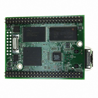
PROCESSOR MODULE FLASH MOD5272
Manufacturer
NetBurner Inc
Type
Controllers & Processorsr
Datasheets
1.MOD5272-100IR.pdf
(2 pages)
2.MOD5272-100IR.pdf
(3 pages)
3.MOD5272-100IR.pdf
(550 pages)
Specifications of MOD5272-100IR
Module/board Type
Processor Module
Ethernet Connection Type
10/100 Ethernet Port RJ-45
Operating Voltage
3.3 V
Product
Modules
Lead Free Status / RoHS Status
Lead free / RoHS Compliant
For Use With/related Products
MOD5272
For Use With
528-1001 - KIT DEVELOP NETWORK FOR MOD5272
Lead Free Status / Rohs Status
Lead free / RoHS Compliant
Other names
528-1008


Operation
Figure 16-22 shows a signal configuration for a UART/RS-232 interface.
16.5 Operation
This section describes operation of the clock source generator, transmitter, and receiver.
16.5.1 Transmitter/Receiver Clock Source
CLKIN serves as the basic timing reference for the clock source generator logic, which
consists of a clock generator and a programmable 16+4-bit divider (UDU, UDL, UFPD)
dedicated to the UART. The clock generator cannot produce standard baud rates if CLKIN
is used, so the 16-bit divider should be used.
16.5.1.1 Programmable Divider
As Figure 16-23 shows, the UART transmitter and receiver can use the following clock
sources:
16-20
Request-to-
Send (URT_RTS)
Clock (URT_CLK)
• An external clock signal on the URT_CLK pin that can be divided by 16. When not
• CLKIN supplies an asynchronous clock source that is prescaled by 32 and then
Signal
divided, URT_CLK provides a synchronous clock mode; when divided by 16, it is
asynchronous.
divided by the 16-bit value programmed in UDUn and UDLn. See Section 16.3.11,
“UART Divider Upper/Lower Registers (UDUn/UDLn).” The precision of this
clock source can be tuned using the 4-bit value programmed in UFPDn.
This output can be programmed to be negated or asserted automatically by either the receiver
or the transmitter. It can control serial data flow when connected to a transmitter’s CTS.
The UART’s external clock source. It can be used in 1x or 16x mode. When both the transmitter
and receiver use the timer as the clock source (UCR = 0xDD), the 16x clock is driven out on
UARTCLK. If either the transmitter or receiver use an external clock (1x or 16x), URT_CLK is an
input.
Table 16-15. UART Module Signals (Continued)
Figure 16-22. UART/RS-232 Interface
URT_CTS
URT_RTS
URT_RxD
URT_TxD
UART
MCF5272 User’s Manual
Description
RS-232 Transceiver
DI2
DO2
DI1
DO1
MOTOROLA
Related parts for MOD5272-100IR
Image
Part Number
Description
Manufacturer
Datasheet
Request
R

Part Number:
Description:
Ethernet Modules & Development Tools MOD5272 Processor Board
Manufacturer:
NetBurner Inc
Datasheet:
Part Number:
Description:
Ethernet Modules & Development Tools MOD5272 Industrial Temperature
Manufacturer:
NetBurner Inc
Part Number:
Description:
Ethernet Modules & Development Tools MOD5272 MODULE
Manufacturer:
NetBurner Inc
Datasheet:

Part Number:
Description:
PROCESSOR MODULE FLASH
Manufacturer:
NetBurner Inc
Datasheet:

Part Number:
Description:
Ethernet Modules & Development Tools 32Bit 62MHz Core Module 50Pin DIP
Manufacturer:
NetBurner Inc
Datasheet:

Part Number:
Description:
BOARD SERIAL-ETHERNET 512K FLASH
Manufacturer:
NetBurner Inc
Datasheet:

Part Number:
Description:
PROCESSOR MODULE 512KB FLASH
Manufacturer:
NetBurner Inc
Datasheet:

Part Number:
Description:
DUAL PORT SERIAL-ETHERNET
Manufacturer:
NetBurner Inc
Datasheet:

Part Number:
Description:
PROCESSOR MODULE 512KB FLASH
Manufacturer:
NetBurner Inc
Datasheet:

Part Number:
Description:
MOD5234 10/100 ETHERNET MODULE
Manufacturer:
NetBurner Inc
Datasheet:

Part Number:
Description:
KIT DEVELOP NETWORK FOR MOD5282
Manufacturer:
NetBurner Inc
Datasheet:

Part Number:
Description:
KIT DEVELOP NETWORK FOR MOD5272
Manufacturer:
NetBurner Inc
Datasheet:

Part Number:
Description:
Ethernet ICs 32bit 147MHz CAN-to- Ethnt Device IndTemp
Manufacturer:
NetBurner Inc
Datasheet: