MOD5272-100IR NetBurner Inc, MOD5272-100IR Datasheet - Page 443
MOD5272-100IR
Manufacturer Part Number
MOD5272-100IR
Description
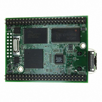
PROCESSOR MODULE FLASH MOD5272
Manufacturer
NetBurner Inc
Type
Controllers & Processorsr
Datasheets
1.MOD5272-100IR.pdf
(2 pages)
2.MOD5272-100IR.pdf
(3 pages)
3.MOD5272-100IR.pdf
(550 pages)
Specifications of MOD5272-100IR
Module/board Type
Processor Module
Ethernet Connection Type
10/100 Ethernet Port RJ-45
Operating Voltage
3.3 V
Product
Modules
Lead Free Status / RoHS Status
Lead free / RoHS Compliant
For Use With/related Products
MOD5272
For Use With
528-1001 - KIT DEVELOP NETWORK FOR MOD5272
Lead Free Status / Rohs Status
Lead free / RoHS Compliant
Other names
528-1008


MOTOROLA
19.13.10 Receive Error (E_RxER/PB14)
Ethernet mode: E_RxER is an input signal which when asserted along with E_RxDV
signals that the PHY has detected an error in the current frame. When E_RxDV is not
asserted E_RxER has no effect. Applies to MII mode operation.
Port B mode: This pin can also be configured as PB14 I/O.
19.13.11 Management Data Clock (E_MDC/PB15)
Ethernet mode: E_MDC is an output clock which provides a timing reference to the PHY
for data transfers on the E_MDIO signal. Applies to MII mode operation.
Port B mode: This pin can also be configured as I/O pin PB15.
19.13.12 Management Data (E_MDIO)
The bidirectional E_MDIO signal transfers control information between the external PHY
and the media-access controller. Data is synchronous to E_MDC. Applies to MII mode
operation. This signal is an input after reset. When the FEC is operated in 10Mbps 7-wire
interface mode, this signal should be connected to Vss.
19.13.13 Transmit Error (E_TxER)
Ethernet mode: When the E_TxER output is asserted for one or more clock cycles while
E_TxEN is also asserted, the PHY sends one or more illegal symbols. E_TxER has no
effect at 10 Mbps or when E_TxEN is negated. Applies to MII mode operation.
19.13.14 Carrier Receive Sense (E_CRS)
E_CRS is an input signal which when asserted signals that transmit or receive medium is
not idle. Applies to MII mode operation.
19.14 PWM Module Signals
PWM_OUT0–PWM_OUT2 are the outputs of the compare logic within the pulse-width
modulator (PWM) modules.
• PWM_OUT0 is always available.
• PWM_OUT1 is multiplexed with TOUT1.
• PWM_OUT2 is multiplexed with TIN1.
(PWM_OUT0–PWM_OUT2])
Chapter 19. Signal Descriptions
PWM Module Signals (PWM_OUT0–PWM_OUT2])
19-29
Related parts for MOD5272-100IR
Image
Part Number
Description
Manufacturer
Datasheet
Request
R

Part Number:
Description:
Ethernet Modules & Development Tools MOD5272 Processor Board
Manufacturer:
NetBurner Inc
Datasheet:
Part Number:
Description:
Ethernet Modules & Development Tools MOD5272 Industrial Temperature
Manufacturer:
NetBurner Inc
Part Number:
Description:
Ethernet Modules & Development Tools MOD5272 MODULE
Manufacturer:
NetBurner Inc
Datasheet:

Part Number:
Description:
PROCESSOR MODULE FLASH
Manufacturer:
NetBurner Inc
Datasheet:

Part Number:
Description:
Ethernet Modules & Development Tools 32Bit 62MHz Core Module 50Pin DIP
Manufacturer:
NetBurner Inc
Datasheet:

Part Number:
Description:
BOARD SERIAL-ETHERNET 512K FLASH
Manufacturer:
NetBurner Inc
Datasheet:

Part Number:
Description:
PROCESSOR MODULE 512KB FLASH
Manufacturer:
NetBurner Inc
Datasheet:

Part Number:
Description:
DUAL PORT SERIAL-ETHERNET
Manufacturer:
NetBurner Inc
Datasheet:

Part Number:
Description:
PROCESSOR MODULE 512KB FLASH
Manufacturer:
NetBurner Inc
Datasheet:

Part Number:
Description:
MOD5234 10/100 ETHERNET MODULE
Manufacturer:
NetBurner Inc
Datasheet:

Part Number:
Description:
KIT DEVELOP NETWORK FOR MOD5282
Manufacturer:
NetBurner Inc
Datasheet:

Part Number:
Description:
KIT DEVELOP NETWORK FOR MOD5272
Manufacturer:
NetBurner Inc
Datasheet:

Part Number:
Description:
Ethernet ICs 32bit 147MHz CAN-to- Ethnt Device IndTemp
Manufacturer:
NetBurner Inc
Datasheet: