MOD5272-100IR NetBurner Inc, MOD5272-100IR Datasheet - Page 136
MOD5272-100IR
Manufacturer Part Number
MOD5272-100IR
Description
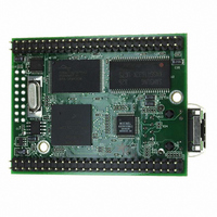
PROCESSOR MODULE FLASH MOD5272
Manufacturer
NetBurner Inc
Type
Controllers & Processorsr
Datasheets
1.MOD5272-100IR.pdf
(2 pages)
2.MOD5272-100IR.pdf
(3 pages)
3.MOD5272-100IR.pdf
(550 pages)
Specifications of MOD5272-100IR
Module/board Type
Processor Module
Ethernet Connection Type
10/100 Ethernet Port RJ-45
Operating Voltage
3.3 V
Product
Modules
Lead Free Status / RoHS Status
Lead free / RoHS Compliant
For Use With/related Products
MOD5272
For Use With
528-1001 - KIT DEVELOP NETWORK FOR MOD5272
Lead Free Status / Rohs Status
Lead free / RoHS Compliant
Other names
528-1008


DRc[4–0]
Programming Model
A write to TDR clears the CSR trigger status bits, CSR[BSTAT].
Table 5-14 describes TDR fields.
5-14
31–30
15–14
28–22
29/13
28/12
27/11
26/10
12–6
25/9
24/8
23/7
22/6
Bits
Reset
Reset
Field
Field
R/W Write only. Accessible in supervisor mode as debug control register 0x07 using the WDEBUG instruction and
through the BDM port using the
Name
31
15
TRC
EBL
EDx
TRC
—
—
30
14
The debug module has no hardware interlocks, so to prevent
spurious breakpoint triggers while the breakpoint registers are
being loaded, disable TDR (by clearing TDR[29,13])before
defining triggers.
Trigger response control. Determines how the processor responds to a completed trigger condition.
The trigger response is always displayed on DDATA.
00 Display on DDATA only
01 Processor halt
10 Debug interrupt
11 Reserved
Reserved, should be cleared.
Enable breakpoint. Global enable for the breakpoint trigger. Setting TDR[EBL] enables a breakpoint
trigger. Clearing it disables all breakpoints at that level.
Setting an EDx bit enables the corresponding data breakpoint condition based on the size and
placement on the processor’s local data bus. Clearing all EDx bits disables data breakpoints.
EDLW
EDWL
EDWU Upper data word.
EDLL
EDLM
EDUM
EDUU
EBL
EBL
29
13
EDLW EDWL EDWU EDLL EDLM EDUM EDUU
EDLW EDWL EDWU EDLL EDLM EDUM EDUU
Figure 5-11. Trigger Definition Register (TDR)
Data longword. Entire processor’s local data bus.
Lower data word.
Lower lower data byte. Low-order byte of the low-order word.
Lower middle data byte. High-order byte of the low-order word.
Upper middle data byte. Low-order byte of the high-order word.
Upper upper data byte. High-order byte of the high-order word.
28
12
Table 5-14. TDR Field Descriptions
27
11
WDMREG
26
10
MCF5272 User’s Manual
command.
0000_0000_0000_0000
0000_0000_0000_0000
25
9
NOTE:
Second-Level Trigger
24
First-Level Trigger
8
Description
0x07
23
7
22
6
21
DI
DI
5
EAI EAR EAL EPC PCI
EAI EAR EAL EPC PCI
20
4
19
3
18
2
MOTOROLA
17
1
16
0
Related parts for MOD5272-100IR
Image
Part Number
Description
Manufacturer
Datasheet
Request
R

Part Number:
Description:
Ethernet Modules & Development Tools MOD5272 Processor Board
Manufacturer:
NetBurner Inc
Datasheet:
Part Number:
Description:
Ethernet Modules & Development Tools MOD5272 Industrial Temperature
Manufacturer:
NetBurner Inc
Part Number:
Description:
Ethernet Modules & Development Tools MOD5272 MODULE
Manufacturer:
NetBurner Inc
Datasheet:

Part Number:
Description:
PROCESSOR MODULE FLASH
Manufacturer:
NetBurner Inc
Datasheet:

Part Number:
Description:
Ethernet Modules & Development Tools 32Bit 62MHz Core Module 50Pin DIP
Manufacturer:
NetBurner Inc
Datasheet:

Part Number:
Description:
BOARD SERIAL-ETHERNET 512K FLASH
Manufacturer:
NetBurner Inc
Datasheet:

Part Number:
Description:
PROCESSOR MODULE 512KB FLASH
Manufacturer:
NetBurner Inc
Datasheet:

Part Number:
Description:
DUAL PORT SERIAL-ETHERNET
Manufacturer:
NetBurner Inc
Datasheet:

Part Number:
Description:
PROCESSOR MODULE 512KB FLASH
Manufacturer:
NetBurner Inc
Datasheet:

Part Number:
Description:
MOD5234 10/100 ETHERNET MODULE
Manufacturer:
NetBurner Inc
Datasheet:

Part Number:
Description:
KIT DEVELOP NETWORK FOR MOD5282
Manufacturer:
NetBurner Inc
Datasheet:

Part Number:
Description:
KIT DEVELOP NETWORK FOR MOD5272
Manufacturer:
NetBurner Inc
Datasheet:

Part Number:
Description:
Ethernet ICs 32bit 147MHz CAN-to- Ethnt Device IndTemp
Manufacturer:
NetBurner Inc
Datasheet: