MOD5272-100IR NetBurner Inc, MOD5272-100IR Datasheet - Page 445
MOD5272-100IR
Manufacturer Part Number
MOD5272-100IR
Description
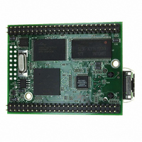
PROCESSOR MODULE FLASH MOD5272
Manufacturer
NetBurner Inc
Type
Controllers & Processorsr
Datasheets
1.MOD5272-100IR.pdf
(2 pages)
2.MOD5272-100IR.pdf
(3 pages)
3.MOD5272-100IR.pdf
(550 pages)
Specifications of MOD5272-100IR
Module/board Type
Processor Module
Ethernet Connection Type
10/100 Ethernet Port RJ-45
Operating Voltage
3.3 V
Product
Modules
Lead Free Status / RoHS Status
Lead free / RoHS Compliant
For Use With/related Products
MOD5272
For Use With
528-1001 - KIT DEVELOP NETWORK FOR MOD5272
Lead Free Status / Rohs Status
Lead free / RoHS Compliant
Other names
528-1008


MOTOROLA
19.15.5 Synchronous Peripheral Chip Select 1
See Section 19.16.1.9, “QSPI Chip Select 1 (QSPI_CS1/PA11).”
QSPI_CS1 can be programmed to be active high or low.
19.15.6 Synchronous Peripheral Chip Select 2
See Section 19.16.1.5, “UART1 CTS (URT1_CTS/QSPI_CS2).”
19.15.7 Synchronous Peripheral Chip Select 3
See
(PA7/DOUT3/QSPI_CS3).” See description for GPIO ports.
19.16 Physical Layer Interface Controller TDM Ports
The MCF5272 has four dedicated physical layer interface ports for connecting to external
ISDN transceivers, CODECs and other peripherals. There are three sets of pins for these
interfaces. Port 0 has its own dedicated set of pins. Ports 1, 2, and 3 share a set of pins.
Port 3 can also be configured to use a dedicated pin set. Ports 1, 2, and 3 always share the
same data clock (DCL).
19.16.1 GCI/IDL TDM Port 0.
This section describes signals used by the PLIC module port 0 interface.
19.16.1.1 Frame Sync (FSR0/FSC0/PA8)
IDL mode: FSR0 is an input for the 8-KHz frame sync for port 0.
GCI mode: FSC0 is an input for the 8-KHz frame sync for port 0. It is active high in this
mode. Normally the GCI FSC signal is two clocks wide and is aligned with the first
B-channel bit of the GCI frame. Many U-interface devices including the MC145572 and
MC145576 change the width of FSC to one clock every 12 mS. This indicates U-interface
super frame boundary.
Port A mode: This pin can be independently configured as PA8.
Section 19.16.3.3,
and UART 1
(QSPI_CS1/PA11)
(QSPI_CS2/URT1_CTS)
(PA7/DOUT3/QSPI_CS3)
“QSPI_CS3,
Chapter 19. Signal Descriptions
Physical Layer Interface Controller TDM Ports and UART 1
Port
3
GCI/IDL
Data
Out
3,
19-31
PA7
Related parts for MOD5272-100IR
Image
Part Number
Description
Manufacturer
Datasheet
Request
R

Part Number:
Description:
Ethernet Modules & Development Tools MOD5272 Processor Board
Manufacturer:
NetBurner Inc
Datasheet:
Part Number:
Description:
Ethernet Modules & Development Tools MOD5272 Industrial Temperature
Manufacturer:
NetBurner Inc
Part Number:
Description:
Ethernet Modules & Development Tools MOD5272 MODULE
Manufacturer:
NetBurner Inc
Datasheet:

Part Number:
Description:
PROCESSOR MODULE FLASH
Manufacturer:
NetBurner Inc
Datasheet:

Part Number:
Description:
Ethernet Modules & Development Tools 32Bit 62MHz Core Module 50Pin DIP
Manufacturer:
NetBurner Inc
Datasheet:

Part Number:
Description:
BOARD SERIAL-ETHERNET 512K FLASH
Manufacturer:
NetBurner Inc
Datasheet:

Part Number:
Description:
PROCESSOR MODULE 512KB FLASH
Manufacturer:
NetBurner Inc
Datasheet:

Part Number:
Description:
DUAL PORT SERIAL-ETHERNET
Manufacturer:
NetBurner Inc
Datasheet:

Part Number:
Description:
PROCESSOR MODULE 512KB FLASH
Manufacturer:
NetBurner Inc
Datasheet:

Part Number:
Description:
MOD5234 10/100 ETHERNET MODULE
Manufacturer:
NetBurner Inc
Datasheet:

Part Number:
Description:
KIT DEVELOP NETWORK FOR MOD5282
Manufacturer:
NetBurner Inc
Datasheet:

Part Number:
Description:
KIT DEVELOP NETWORK FOR MOD5272
Manufacturer:
NetBurner Inc
Datasheet:

Part Number:
Description:
Ethernet ICs 32bit 147MHz CAN-to- Ethnt Device IndTemp
Manufacturer:
NetBurner Inc
Datasheet: