MOD5272-100IR NetBurner Inc, MOD5272-100IR Datasheet - Page 479
MOD5272-100IR
Manufacturer Part Number
MOD5272-100IR
Description
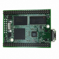
PROCESSOR MODULE FLASH MOD5272
Manufacturer
NetBurner Inc
Type
Controllers & Processorsr
Datasheets
1.MOD5272-100IR.pdf
(2 pages)
2.MOD5272-100IR.pdf
(3 pages)
3.MOD5272-100IR.pdf
(550 pages)
Specifications of MOD5272-100IR
Module/board Type
Processor Module
Ethernet Connection Type
10/100 Ethernet Port RJ-45
Operating Voltage
3.3 V
Product
Modules
Lead Free Status / RoHS Status
Lead free / RoHS Compliant
For Use With/related Products
MOD5272
For Use With
528-1001 - KIT DEVELOP NETWORK FOR MOD5272
Lead Free Status / Rohs Status
Lead free / RoHS Compliant
Other names
528-1008


MOTOROLA
as RSTI is asserted and remains asserted for 32,768 CLKIN cycles after RSTI is negated.
For proper normal reset operation, DRESETEN must be negated as long as RSTI is
asserted.
The levels of the mode select inputs, QSPI_Dout/WSEL, QSPI_CLK/BUSW1, and
QSPI_CS0/BUSW0, are sampled when RSTI negates and select the port size of CS0 and
the physical data bus width after a master reset occurs. The INTx signals are synchronized
and are registered on the last falling edge of CLKIN where RSTI is asserted.
During the normal reset period, all outputs are driven to their default levels. Once RSTO
negates, all bus signals continue to remain in this state until the ColdFire core begins the
first bus cycle for reset exception processing.
A normal reset causes all bus activity except SDRAM refresh cycles to terminate. During
a normal reset, SDRAM refresh cycles continue to occur at the programmed rate and with
the programmed waveform timing. In addition, normal reset initializes registers
appropriately for a reset exception. During a normal reset, SCR[RSTSRC] is set to 0b01 to
indicate assertion of RSTI with DRESETEN negated caused the previous reset.
20.12.3 Software Watchdog Timer Reset Operation
A software watchdog timer is provided to allow periodic monitoring of software activity. If
the software watchdog is not periodically accessed by software it can programmed to
generate a reset after a timeout period. When the timeout occurs, an internal reset is asserted
for 32K clocks, resetting internal registers as with a normal reset. The RSTO pin
simultaneously asserts for 32K clocks after the software watchdog timeout. Figure 20-23
illustrates the timing of RSTO when asserted by a software watchdog timeout.
CLKIN
SOFTWARE
WATCHDOG
TIMEOUT
INTERNAL
RSTI
RSTO
BUS SIGNALS
Figure 20-23. Software Watchdog Timer Reset Timing
Chapter 20. Bus Operation
CLKIN CYCLES
T = 32K
Reset Operation
20-25
Related parts for MOD5272-100IR
Image
Part Number
Description
Manufacturer
Datasheet
Request
R

Part Number:
Description:
Ethernet Modules & Development Tools MOD5272 Processor Board
Manufacturer:
NetBurner Inc
Datasheet:
Part Number:
Description:
Ethernet Modules & Development Tools MOD5272 Industrial Temperature
Manufacturer:
NetBurner Inc
Part Number:
Description:
Ethernet Modules & Development Tools MOD5272 MODULE
Manufacturer:
NetBurner Inc
Datasheet:

Part Number:
Description:
PROCESSOR MODULE FLASH
Manufacturer:
NetBurner Inc
Datasheet:

Part Number:
Description:
Ethernet Modules & Development Tools 32Bit 62MHz Core Module 50Pin DIP
Manufacturer:
NetBurner Inc
Datasheet:

Part Number:
Description:
BOARD SERIAL-ETHERNET 512K FLASH
Manufacturer:
NetBurner Inc
Datasheet:

Part Number:
Description:
PROCESSOR MODULE 512KB FLASH
Manufacturer:
NetBurner Inc
Datasheet:

Part Number:
Description:
DUAL PORT SERIAL-ETHERNET
Manufacturer:
NetBurner Inc
Datasheet:

Part Number:
Description:
PROCESSOR MODULE 512KB FLASH
Manufacturer:
NetBurner Inc
Datasheet:

Part Number:
Description:
MOD5234 10/100 ETHERNET MODULE
Manufacturer:
NetBurner Inc
Datasheet:

Part Number:
Description:
KIT DEVELOP NETWORK FOR MOD5282
Manufacturer:
NetBurner Inc
Datasheet:

Part Number:
Description:
KIT DEVELOP NETWORK FOR MOD5272
Manufacturer:
NetBurner Inc
Datasheet:

Part Number:
Description:
Ethernet ICs 32bit 147MHz CAN-to- Ethnt Device IndTemp
Manufacturer:
NetBurner Inc
Datasheet: