MOD5272-100IR NetBurner Inc, MOD5272-100IR Datasheet - Page 388
MOD5272-100IR
Manufacturer Part Number
MOD5272-100IR
Description
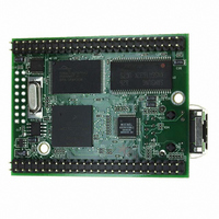
PROCESSOR MODULE FLASH MOD5272
Manufacturer
NetBurner Inc
Type
Controllers & Processorsr
Datasheets
1.MOD5272-100IR.pdf
(2 pages)
2.MOD5272-100IR.pdf
(3 pages)
3.MOD5272-100IR.pdf
(550 pages)
Specifications of MOD5272-100IR
Module/board Type
Processor Module
Ethernet Connection Type
10/100 Ethernet Port RJ-45
Operating Voltage
3.3 V
Product
Modules
Lead Free Status / RoHS Status
Lead free / RoHS Compliant
For Use With/related Products
MOD5272
For Use With
528-1001 - KIT DEVELOP NETWORK FOR MOD5272
Lead Free Status / Rohs Status
Lead free / RoHS Compliant
Other names
528-1008


Operation
16.5.3 Looping Modes
The UART can be configured to operate in various looping modes as shown in
Figure 16-26. These modes are useful for local and remote system diagnostic functions and
are described in the following paragraphs and in Section 16.3, “Register Descriptions.”
The UART’s transmitter and receiver should be disabled when switching between modes,
as the selected mode is activated immediately upon mode selection, regardless of whether
a character is being received or transmitted.
16.5.3.1 Automatic Echo Mode
In automatic echo mode, shown in Figure 16-27, the UART automatically resends received
data bit by bit. The local CPU-to-receiver communication continues normally, but the
CPU-to-transmitter link is disabled. In this mode, received data is clocked on the receiver
clock and resent on TxD. The receiver must be enabled, but the transmitter need not be.
Because the transmitter is inactive, USRn[TxEMP,TxRDY] are inactive and data is sent as
it is received. Received parity is checked but is not recalculated for transmission. Character
framing is also checked, but stop bits are sent as they are received. A received break is
echoed as received until the next valid start bit is detected. Autobaud operation does not
affect automatic echo mode; that is, the first character received is correctly echoed back.
16.5.3.2 Local Loop-Back Mode
Figure 16-28 shows how TxD and RxD are internally connected in local loop-back mode.
This mode is for testing the operation of a local UART module channel by sending data to
the transmitter and checking data assembled by the receiver to ensure proper operations.
Features of this local loop-back mode are as follows:
16-28
• Transmitter and CPU-to-receiver communications continue normally in this mode.
• RxD input data is ignored
• TxD is held marking
• The receiver is clocked by the transmitter clock. The transmitter must be enabled,
but the receiver need not be.
CPU
CPU
Disabled
Figure 16-28. Local Loop-Back
Figure 16-27. Automatic Echo
MCF5272 User’s Manual
Rx
Tx
Rx
Tx
Disabled
Disabled
Disabled
RxD Input
TxD Input
RxD Input
TxD Input
MOTOROLA
Related parts for MOD5272-100IR
Image
Part Number
Description
Manufacturer
Datasheet
Request
R

Part Number:
Description:
Ethernet Modules & Development Tools MOD5272 Processor Board
Manufacturer:
NetBurner Inc
Datasheet:
Part Number:
Description:
Ethernet Modules & Development Tools MOD5272 Industrial Temperature
Manufacturer:
NetBurner Inc
Part Number:
Description:
Ethernet Modules & Development Tools MOD5272 MODULE
Manufacturer:
NetBurner Inc
Datasheet:

Part Number:
Description:
PROCESSOR MODULE FLASH
Manufacturer:
NetBurner Inc
Datasheet:

Part Number:
Description:
Ethernet Modules & Development Tools 32Bit 62MHz Core Module 50Pin DIP
Manufacturer:
NetBurner Inc
Datasheet:

Part Number:
Description:
BOARD SERIAL-ETHERNET 512K FLASH
Manufacturer:
NetBurner Inc
Datasheet:

Part Number:
Description:
PROCESSOR MODULE 512KB FLASH
Manufacturer:
NetBurner Inc
Datasheet:

Part Number:
Description:
DUAL PORT SERIAL-ETHERNET
Manufacturer:
NetBurner Inc
Datasheet:

Part Number:
Description:
PROCESSOR MODULE 512KB FLASH
Manufacturer:
NetBurner Inc
Datasheet:

Part Number:
Description:
MOD5234 10/100 ETHERNET MODULE
Manufacturer:
NetBurner Inc
Datasheet:

Part Number:
Description:
KIT DEVELOP NETWORK FOR MOD5282
Manufacturer:
NetBurner Inc
Datasheet:

Part Number:
Description:
KIT DEVELOP NETWORK FOR MOD5272
Manufacturer:
NetBurner Inc
Datasheet:

Part Number:
Description:
Ethernet ICs 32bit 147MHz CAN-to- Ethnt Device IndTemp
Manufacturer:
NetBurner Inc
Datasheet: