MOD5272-100IR NetBurner Inc, MOD5272-100IR Datasheet - Page 87
MOD5272-100IR
Manufacturer Part Number
MOD5272-100IR
Description
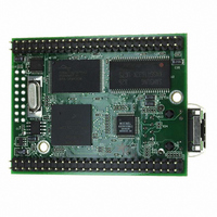
PROCESSOR MODULE FLASH MOD5272
Manufacturer
NetBurner Inc
Type
Controllers & Processorsr
Datasheets
1.MOD5272-100IR.pdf
(2 pages)
2.MOD5272-100IR.pdf
(3 pages)
3.MOD5272-100IR.pdf
(550 pages)
Specifications of MOD5272-100IR
Module/board Type
Processor Module
Ethernet Connection Type
10/100 Ethernet Port RJ-45
Operating Voltage
3.3 V
Product
Modules
Lead Free Status / RoHS Status
Lead free / RoHS Compliant
For Use With/related Products
MOD5272
For Use With
528-1001 - KIT DEVELOP NETWORK FOR MOD5272
Lead Free Status / Rohs Status
Lead free / RoHS Compliant
Other names
528-1008


1
TRAPF
TST
UNLK
WDDATA
Instruction
1
execution by setting CSR[UHE].
By default the HALT instruction is a supervisor-mode instruction; however, it can be configured to allow user-mode
CPUSHL
HALT
MOVE from SR
MOVE to SR
MOVEC
RTE
STOP
WDEBUG
MOTOROLA
Table 2-8 describes supervisor-mode instructions.
2.7 Instruction Timing
The timing data presented in this section assumes the following:
The HALT instruction can be configured to allow user-mode execution by setting CSR[UHE].
Instruction
• The OEP is loaded with the opword and all required extension words at the
• The OEP experiences no sequence-related pipeline stalls. For the MCF5272,the
1
beginning of each instruction execution. This implies that the OEP spends no time
waiting for the IFP to supply opwords and/or extension words.
most common example of this type of stall involves consecutive store operations,
excluding the MOVEM instruction. For all store operations (except MOVEM),
None
#<data>
<ea>y
Ax
<ea>y
Operand Syntax
Table 2-7. User-Mode Instruction Set Summary (Continued)
(bc),(Ax)
none
SR, Dx
Dy,SR
#<data>,SR
Ry,Rc
None
#<data>
<ea-2>y
Operand Syntax Operand Size
Table 2-8. Supervisor-Mode Instruction Set Summary
Unsized
.W
.L
.B,.W,.L
Unsized
.B,.W,.L
Unsized
Unsized
.W
.W
.L
Unsized
.W
.L
Operand Size
Chapter 2. ColdFire Core
Invalidate instruction cache line
Enter halted state
SR → Dx
Source → SR
Ry → Rc
Rc
0x002
0x004
0x005
0x801
0xC00 ROM base address register (ROMBAR)
0xC04 RAM base address register (RAMBAR)
0xC0F Module base address register (MBAR)
(SP+2) → SR; SP+4 → SP; (SP) → PC; SP + formatfield SP
Immediate data → SR; enter stopped state
<ea-2>y → debug module
PC + 2 → PC
PC + 4 → PC
PC + 6 → PC
Set condition codes
Ax →SP; (SP) → Ax; SP + 4 → SP
<ea>y →DDATA port
Register Definition
Cache control register (CACR)
Access control register 0 (ACR0)
Access control register 1 (ACR1)
Vector base register (VBR)
Operation
Operation
Instruction Timing
2-19
Related parts for MOD5272-100IR
Image
Part Number
Description
Manufacturer
Datasheet
Request
R

Part Number:
Description:
Ethernet Modules & Development Tools MOD5272 Processor Board
Manufacturer:
NetBurner Inc
Datasheet:
Part Number:
Description:
Ethernet Modules & Development Tools MOD5272 Industrial Temperature
Manufacturer:
NetBurner Inc
Part Number:
Description:
Ethernet Modules & Development Tools MOD5272 MODULE
Manufacturer:
NetBurner Inc
Datasheet:

Part Number:
Description:
PROCESSOR MODULE FLASH
Manufacturer:
NetBurner Inc
Datasheet:

Part Number:
Description:
Ethernet Modules & Development Tools 32Bit 62MHz Core Module 50Pin DIP
Manufacturer:
NetBurner Inc
Datasheet:

Part Number:
Description:
BOARD SERIAL-ETHERNET 512K FLASH
Manufacturer:
NetBurner Inc
Datasheet:

Part Number:
Description:
PROCESSOR MODULE 512KB FLASH
Manufacturer:
NetBurner Inc
Datasheet:

Part Number:
Description:
DUAL PORT SERIAL-ETHERNET
Manufacturer:
NetBurner Inc
Datasheet:

Part Number:
Description:
PROCESSOR MODULE 512KB FLASH
Manufacturer:
NetBurner Inc
Datasheet:

Part Number:
Description:
MOD5234 10/100 ETHERNET MODULE
Manufacturer:
NetBurner Inc
Datasheet:

Part Number:
Description:
KIT DEVELOP NETWORK FOR MOD5282
Manufacturer:
NetBurner Inc
Datasheet:

Part Number:
Description:
KIT DEVELOP NETWORK FOR MOD5272
Manufacturer:
NetBurner Inc
Datasheet:

Part Number:
Description:
Ethernet ICs 32bit 147MHz CAN-to- Ethnt Device IndTemp
Manufacturer:
NetBurner Inc
Datasheet: