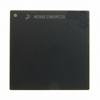
MC68EC060RC50 Freescale Semiconductor, MC68EC060RC50 Datasheet - Page 162

MC68EC060RC50
Manufacturer Part Number
MC68EC060RC50
Description
IC MPU 32BIT 50MHZ 206-PGA
Manufacturer
Freescale Semiconductor
Specifications of MC68EC060RC50
Processor Type
M680x0 32-Bit
Speed
50MHz
Voltage
3.3V
Mounting Type
Surface Mount
Package / Case
206-PGA
Family Name
M68000
Device Core
ColdFire
Device Core Size
32b
Frequency (max)
50MHz
Instruction Set Architecture
RISC
Supply Voltage 1 (typ)
3.3V
Operating Supply Voltage (max)
3.465V
Operating Supply Voltage (min)
3.135V
Operating Temp Range
0C to 110C
Operating Temperature Classification
Commercial
Mounting
Through Hole
Pin Count
206
Package Type
PGA
Lead Free Status / RoHS Status
Contains lead / RoHS non-compliant
Features
-
Lead Free Status / Rohs Status
Compliant
Available stocks
Company
Part Number
Manufacturer
Quantity
Price
Company:
Part Number:
MC68EC060RC50
Manufacturer:
NXP
Quantity:
1 746
- Current page: 162 of 416
- Download datasheet (2Mb)
Table 7-1 lists the combinations of the SIZx, A1, and A0 signals, collectively called byte
enable signals, that are used for each of the four sections of the data bus. Alternatively, the
BSx signals may be used for byte selection. In Table 7-1, OP0–OP3 indicates the portion of
the requested operand that is read or written during that bus transfer. For line and long-word
transfers, all bytes are valid as listed and can correspond to portions of the requested oper-
and or to data required to fill the remainder of the cache line. The bytes labeled with a dash
are not required; they are ignored on read transfers and driven with undefined data on write
transfers. Not selecting these bytes prevents incorrect accesses in sensitive areas such as
I/O devices. Figure 7-8 illustrates a logic diagram for one method for generating byte select
signals from SIZx, A1, and A0 and the associated PAL equation. The logic shown in Figure
7-8 is equivalent to the internal logic used to generate the external byte select signals (BSx)
provided by the processor. Byte enable signals derived from the SIZx, A1, and A0 signals,
or alternatively, the external BSx signals, can be combined with the address or other
attributes signals to generate the decode logic of a system.
The MC68060 provides BSx so that it is unnecessary to use the SIZx, A1, and A0 signals to
generate byte selects using external logic. This aids in high-speed system design. Figure 7-
7, Figure 7-8, and Table 7-1 show the relationship between SIZx, A1, A0, and BSx.
A brief summary of the bus signal encoding for each access type is listed in Table 7-2. Addi-
tional information on the encoding for the MC68060 signals can be found in Section 2 Sig-
nal Description .
MOTOROLA
Transfer Size
Long Word
Word
Byte
Line
Table 7-1. Data Bus Requirements for Read and Write Cycles
SIZ1
0
0
0
0
1
1
0
1
Signal Encoding
SIZ0
1
1
1
1
0
0
0
1
A1
X
X
0
0
1
1
0
1
M68060 USER’S MANUAL
A0
X
X
0
1
0
1
0
0
D31–D24
OP3
OP2
OP0
OP0
BS0
—
—
—
—
Active Data Bus Sections and Byte Enables
D23–D16
BS1
OP3
OP3
OP1
OP1
—
—
—
—
D15–D8
BS2
OP3
OP2
OP2
OP2
—
—
—
—
D7–D0
Bus Operation
BS3
OP3
OP3
OP3
OP3
—
—
—
—
7-7
Related parts for MC68EC060RC50
Image
Part Number
Description
Manufacturer
Datasheet
Request
R
Part Number:
Description:
Manufacturer:
Freescale Semiconductor, Inc
Datasheet:
Part Number:
Description:
Manufacturer:
Freescale Semiconductor, Inc
Datasheet:
Part Number:
Description:
Manufacturer:
Freescale Semiconductor, Inc
Datasheet:
Part Number:
Description:
Manufacturer:
Freescale Semiconductor, Inc
Datasheet:
Part Number:
Description:
Manufacturer:
Freescale Semiconductor, Inc
Datasheet:
Part Number:
Description:
Manufacturer:
Freescale Semiconductor, Inc
Datasheet:
Part Number:
Description:
Manufacturer:
Freescale Semiconductor, Inc
Datasheet:
Part Number:
Description:
Manufacturer:
Freescale Semiconductor, Inc
Datasheet:
Part Number:
Description:
Manufacturer:
Freescale Semiconductor, Inc
Datasheet:
Part Number:
Description:
Manufacturer:
Freescale Semiconductor, Inc
Datasheet:
Part Number:
Description:
Manufacturer:
Freescale Semiconductor, Inc
Datasheet:
Part Number:
Description:
Manufacturer:
Freescale Semiconductor, Inc
Datasheet:
Part Number:
Description:
Manufacturer:
Freescale Semiconductor, Inc
Datasheet:
Part Number:
Description:
Manufacturer:
Freescale Semiconductor, Inc
Datasheet:
Part Number:
Description:
Manufacturer:
Freescale Semiconductor, Inc
Datasheet:


